
Last Updated: April 13, 2022
Mushrooms are a unique and often mysterious organism. They’re not quite plants and not quite animals. As a fungus, mushrooms represent a distinct evolutionary lineage. Fungi grow as a single-cell yeast form (used in beer, wine, and bread making) and multi-cellular, thread-like mycelia that often produce fruiting bodies (mushrooms) and sclerotia (e.g. truffles), and are responsible for the decomposition of the vast majority of dead plant matter. Understanding life cycle of mushroom fungi is a valuable skill if you wish to harness this knowledge for mushroom cultivation.
There are a variety of edible mushrooms that can be readily cultivated. Button/portobello, oyster, shiitake, and lion’s mane are a few common and hardy species for which reliable cultivation methods have been developed. However, there are a few specific skills and techniques that are necessary if you wish to go through the process of foraging wild mushrooms to cultivating them. This article and accompanying video will demystify this process by demonstrating how mushroom cultivation can be performed with a minimal skill set and budget.
Support
If you find this article or video interesting, useful, or you use Mycodo and want to support my future work and software development, consider becoming a GitHub Sponsor or Patron, or making a donation.
Introduction
Among Eukaryotic organisms, mushrooms belong to the Kingdom Fungi, which is distinct from the two other well-known Kingdoms, Plantae (plants) and Animalia (animals). Interestingly, fungi are more closely related to animals than plants. Fungi are most commonly found as yeasts, molds, and mushrooms. Although they share many similarities, their life cycles can differ significantly. Fungi that produce mushrooms typically have three distinct phases of their growth cycle: 1) colonization as filamentous mycelia, 2) primordia or pre-mushroom formation, and 3) fruiting body or mushroom formation. Each growth stage often requires specific environmental conditions for initiation and to grow optimally. The most influential conditions are air temperature, humidity, and carbon dioxide (CO2) concentration. These growth cycle changes are often a natural response to the change in seasonal conditions that promote producing mushrooms. By harnessing this knowledge, we can optimize conditions to promote specific growth stages. To do this, we will rely on sensors to measure our environmental conditions and relays to control devices to modulate these conditions, then create feedback loops with these inputs and outputs to regulate conditions to our desired state. The hardware is inexpensive off-the-shelf components and the software is a custom environmental control system I developed, Mycodo, and is free and open source. Below is an overview of some of the features of the system we will set up, but do check out GitHub for a full list of features.
Mycodo Features in this Project
- Measure air conditions: temperature, humidity, and carbon dioxide concentration.
- Control relays to operate a humidifier, air pump for sampling carbon dioxide, and lighting for time-lapse photography.
- Generate a pulse-width modulated (PWM) output signal to control fan speed for fresh air exchange.
- Automatically adjust air to target humidity and carbon dioxide concentration ranges by modulating the fan and humidifier.
- Use timers to schedule light & camera captures for time-lapse photography.
- Send e-mail alert notifications if measurements fall outside acceptable ranges (e.g. temperature, humidity, or carbon dioxide too high or low).
- Use the Raspberry Pi Camera to monitor mushrooms with live images and conduct time-lapse photography of growth.
- Configure dashboards with gauges, graphs, camera, and other widgets to view all relevant data on a single page.
- Forward port 443 through your router to the Raspberry Pi to be able to view and control the system with the Mycodo web interface from anywhere with internet access (with a user login system for security).
Disclosures
I reached out to Atlas Scientific to ask if they would be willing to contribute to this project, and they were kind enough to donate a temperature/humidity sensor. I’ve used Atlas Scientific instruments for years and have incorporated support for several of their sensors and devices. I’d like to thank them for their donation and for making quality products.
Additionally, I earn a commission from qualifying purchases. What this means is if you click a link on my site to a product and purchase it, I may earn a small commission, without any additional cost to you. Please consider using these links if you would like to support my work and see more like it in the future.
Materials & Parts List
As needs vary, so too will the choice of materials one incorporates into a system build. The materials list below is only meant to provide a complete list of the components I used in this particular build.
Tools
Laminar Flow Hood
| Description | Purchase | Quantity |
|---|---|---|
| 2020 Extruded Aluminum Rail (1 Meter Span) | Amazon | 10 |
| 2020 6mm T-Slot Corner Brace | Amazon | 14 |
| 2020 6mm Straight Rail Connector | Amazon | 4 |
| 2020 6mm M5 T-Nut | Amazon | 70 |
| M5-0.8 x 8 mm Bolt | Amazon | 70 |
| Fan Unit | Amazon | 1 |
| HEPA Filter (24 inch x 24 inch) | Amazon | 1 |
| 2-foot x 3-foot Poster Frame (for plastic panels) | Local Store | 3 or 4 |
| 2-foot x 2-foot x 3/4-inch Plywood | Hardware Store | 1 |
| 1/2-inch Wood Screw | Hardware Store | 12 |
| Weather Stripping with Adhesive | Amazon | 1 |
| Varnish and Paint Brush | Hardware Store | 1 small can |
| Silicon Sealant | Hardware Store | 1 tube |
| Variable Transformer/Variac (Optional) | Amazon | 1 |
| Digital Multimeter with Current Transformer (Optional) | Amazon | 1 |
| Custom 3D-Printed Case for Digital Multimeter | Free 3D Model Download | 1 |
Isolation & Culture Materials
| Description | Purchase | Quantity |
|---|---|---|
| Nitrile Gloves | Amazon | 1 box |
| Ethanol or Isopropyl Alcohol | Amazon | 1 bottle |
| #11 Scalpel Blades with Metal Handle | Amazon | 1 |
| Reusable Glass Petri Dishes | Amazon | 10 |
| Reusable Metal Petri Dish Sleeve | Amazon | 1 |
| Pressure Cooker | Amazon | 1 |
| Paraffin Film | Amazon | 1 box |
| Aluminum Foil | Amazon | 1 roll |
| Scissors or Trauma Shears | Amazon, Amazon | 1 |
| Powered Light Dry Malt Extract | Amazon | 1 lb bag |
| Powered Agar | Amazon | 1 bottle |
| Bird Seed | Amazon | 1 bag |
| Mushroom Culture (Foraged or Purchased) | 1 | |
| GL45 Glass Bottle | Amazon | 2 pack |
| Wide Mouth Jars (20 oz) | Amazon | 1 pack |
| Milligram Digital Scale | Amazon | 1 |
| Weigh Boats | Amazon | 1 pack |
| Measuring Cup | Amazon | 1 |
Base Mushroom Cultivation System
| Description | Purchase | Quantity |
|---|---|---|
| Grow Tent (24 x 24 x 36 inch) | Amazon | 1 |
| Humidifier | Amazon | 1 |
| 80 mm PC Fan with Power Adapter | Amazon | 1 |
Environmental Monitoring and Regulation System
| Description | Purchase | Quantity |
|---|---|---|
| Raspberry Pi Zero 2 W | Amazon | 1 |
| Custom 3D-Printed Mount for Raspberry Pi Zero | Free 3D Model Download | 1 |
| Ultra-Small Pi Terminal Breakout Module | Amazon | 1 |
| Micro USB Power Switch | Amazon | 1 |
| Micro SD Card (32 GB) | Amazon | 1 |
| DIN Rail | Amazon | 1 |
| DIN Rail Terminal Block Kit | Amazon | 1 Kit |
| Terminal Block Jumpers | Amazon | 1 Pack |
| DIN Rail Mounting Adapters | Amazon | 1 Pack |
| Camera Clamp Mount | Amazon | 1 |
| Raspberry Pi High Quality Camera Module with 6 mm Lens | RaspberyPi.org | 1 |
| Raspberry Pi Zero Camera Ribbon Cable (mini) | Amazon | 1 |
| Raspberry Pi Camera Camera Ribbon Cable (full-size) | Amazon | 1 |
| Raspberry Pi Ribbon Cable Adapter | Adafruit | 1 |
| Temperature and Humidity Sensor | Amazon, Amazon, Amazon, Amazon, DFRobot, DFRobot | 1 |
| MH-Z19B Carbon Dioxide Gas Sensor | Amazon, Tindie | 1 |
| Dupont Crimping Tool and Connectors | Amazon | 1 |
| Project Box Enclosure (approx. 8 x 5 x 3 inch) | Amazon | 1 |
| 20 character, 4 line I2C LCD Display | Amazon, DFRobot | 1 |
| Jumper Wire Kit | Amazon | 1 pack |
| Cable Glands | Amazon | 1 Pack |
| Electronically Controlled Duct Fan (4 inch) | Amazon | 1 |
| Fan Speed Control Board | OSH Park | 3 |
| Panel Mount Audio Jack (for Fan Speed Control Board) | Amazon | 1 Pack |
| Air Filter (4 inch) | Amazon | 1 |
| Ducting (4 inch) | Amazon | 1 |
Electrical Power Control and Sensing
These materials enable the control of electrical devices and monitor the amount of power consumed by the system.
| Description |
|---|
| 3-Outlet Smart WiFi Power Strip |
| Or search the database of Tasmota-supported devices to find an alternative |
Building the Laminar Flow Hood
A laminar flow hood creates a stream of clean, sterile air for you to work in that prevents contaminating microorganisms in the air from coming into contact with what you’re working on. This is an essential piece of equipment when working with microorganisms and mushroom cultures because it significantly reduces the chances of contamination. During the process of cultivating mushrooms, you may be working with sterile agar Petri plates, sterile spawn substrates, sterile growth substrates, and of course mushroom cultures. Any number of microorganisms that normally exist in the air can land on these surfaces and begin growing. These contaminating microorganisms can compete with your mushroom culture by consuming the same growth substrate your mushroom culture is growing on, and in some cases can inhibit the growth of your mushroom culture, produce toxins, release spores, or cause other negative effects from their growth. By using a laminar flow hood with a quality high-efficiency particulate air (HEPA) filter, contamination can be reduced or eliminated entirely.
There are three main parts of this laminar flow hood: the frame, HEPA filter, and fan.
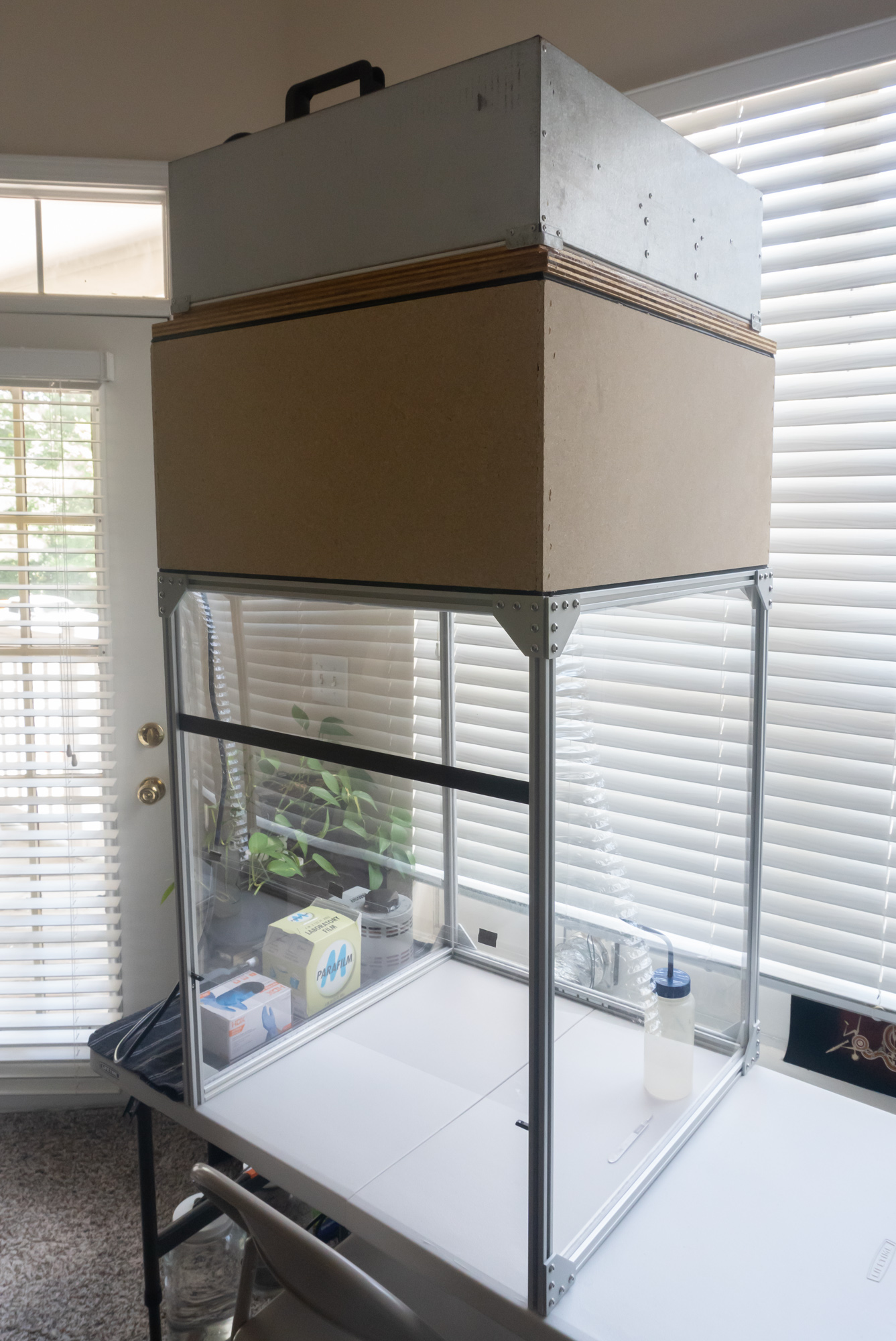
Frame
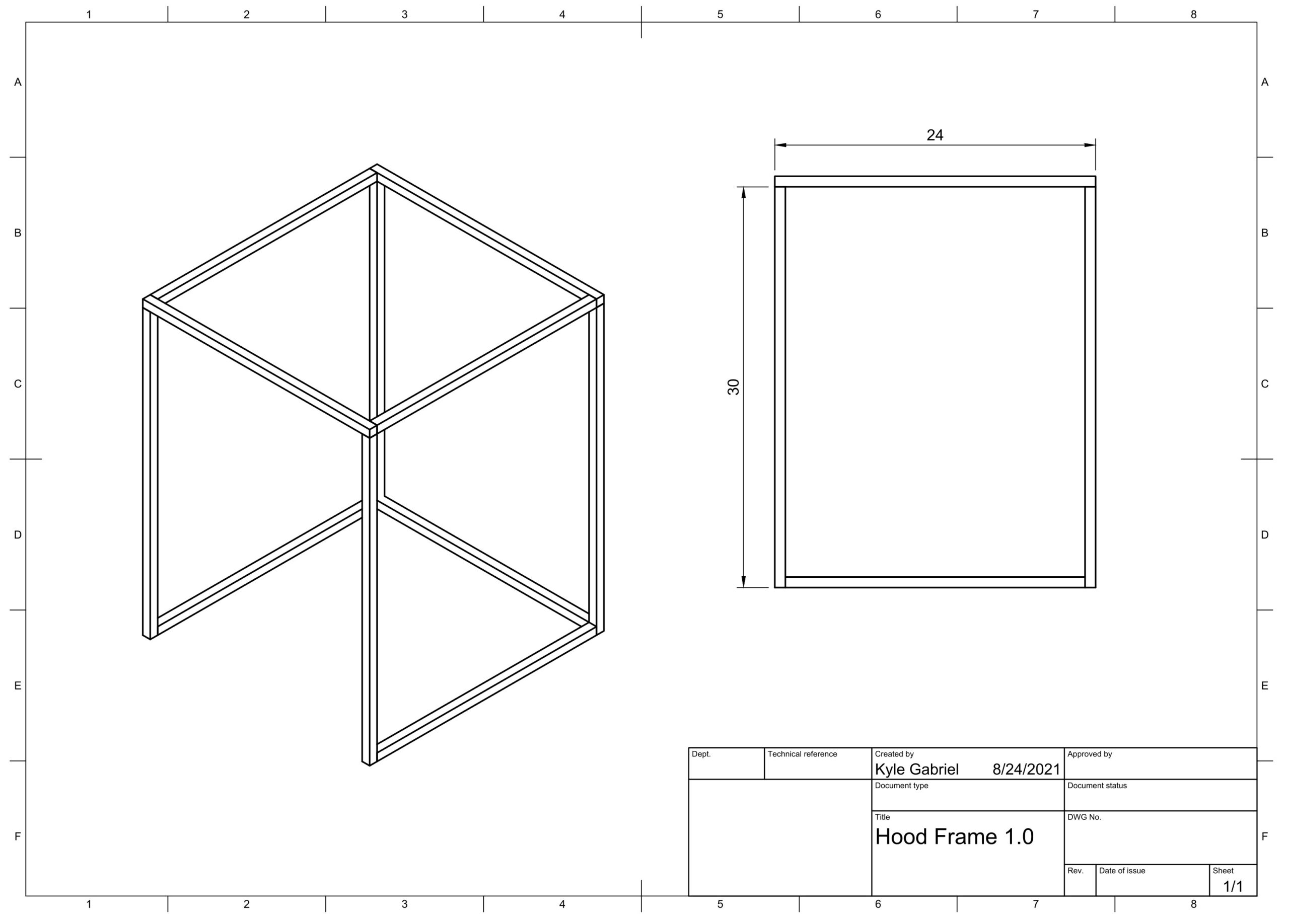
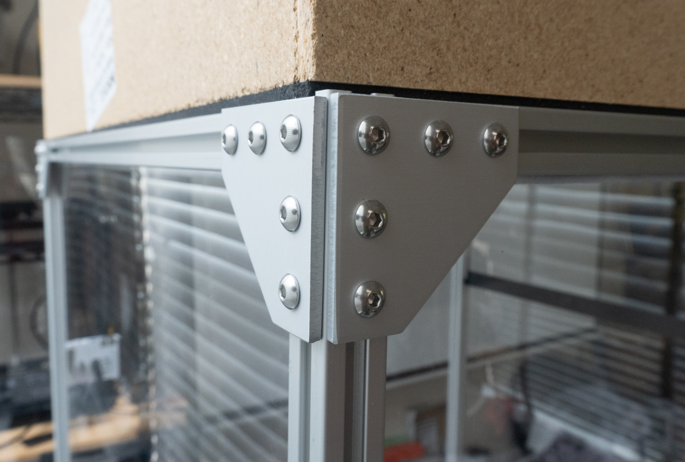
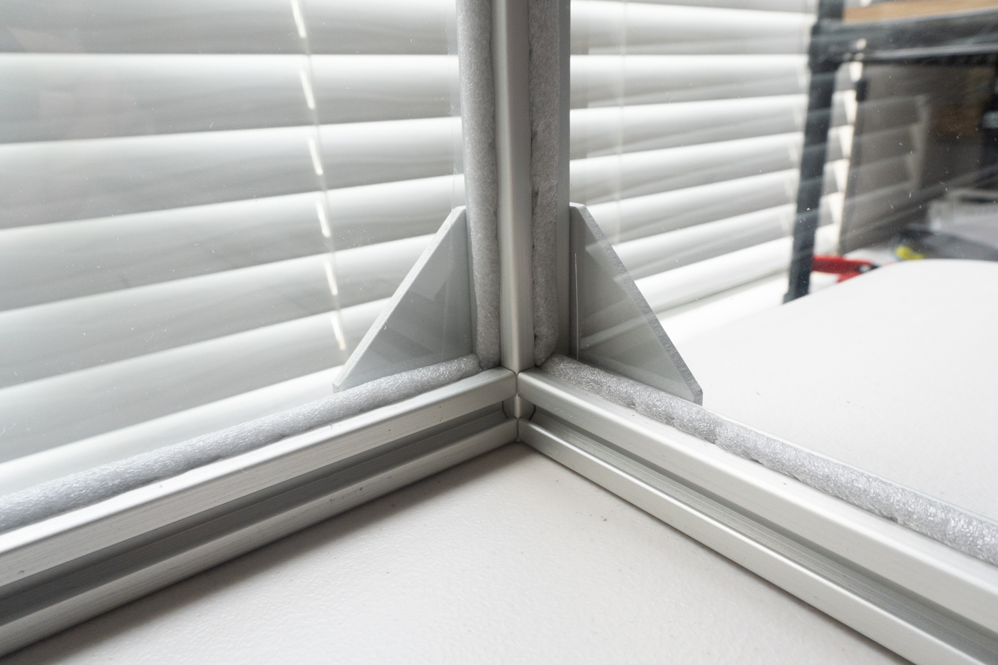
Extruded aluminum rail was used to create a 2 foot x 2 foot x 2.5 foot frame. The frame can be positioned either vertically or horizontally with the blower fan and filter to provide either a 2 x 2 foot or 2 x 2.5 foot working area surface. Corner braces were used to attach the rails using hex huts and rail channel pieces. Adhere a strip of weather stripping between the top of the frame and the HEPA filter to make an air-tight seal.
Plastic sheets from poster frames were cut to fit within the rails and foam insulation was used to secure the plastic to the frame and make a seal. Since there will be positive pressure due to the inflow of sterile air from the HEPA filter, this does not need to be completely air-tight, so this insulation is mainly to improve the rigidity of the thin plastic walls.
Air Filter Adapter
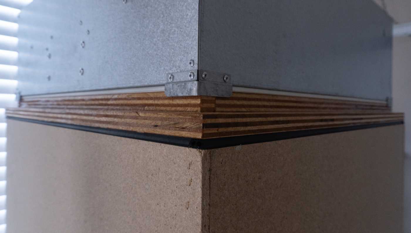
Whether you use the same fan I used or something else, the outflow opening of the fan may not be exactly the size of the HEPA filter. Therefore, you may need to construct an adapter to mate the opening of your fan output to the HEPA filter. I created a simple adapter plate by cutting a piece of plywood to the outer dimensions of the 2 x 2 foot HEPA filter, then used a circular saw to plunge-cut the inner opening to 1 inch smaller than the size of the fan. I then cut 1-inch strips and screwed these as a rail around the entire inner edge for the fan to rest on. Countersink your screws to allow weatherstripping to seal against the wood. Varnish can be used to seal the wood and silicon calk can be used to seal the wooden joints. Last, soft weatherstripping was affixed to the adapter’s edges that come into contact with the fan box and HEPA filter to make an air-tight seal between the blower fan and the HEPA filter.

Assembly
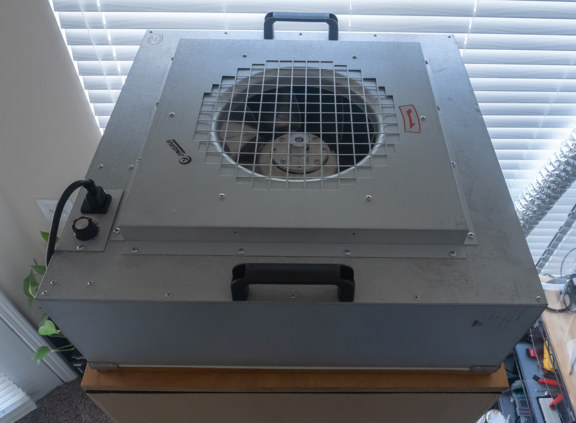
To assemble the flow hood, place the frame upright on a sturdy surface at a good height for comfortably working in. Ensure there is enough clearance above the frame for the HEPA filter and fan to be attached. Next, place the HEPA filter on top of the frame. Place the adapter on top of the filter. Last, place the fan on top of the adapter. Last, ensure a good seal is made on all sides between the frame and HEPA filter, between the HEPA filter and adapter plate, and between the adapter plate and fan.
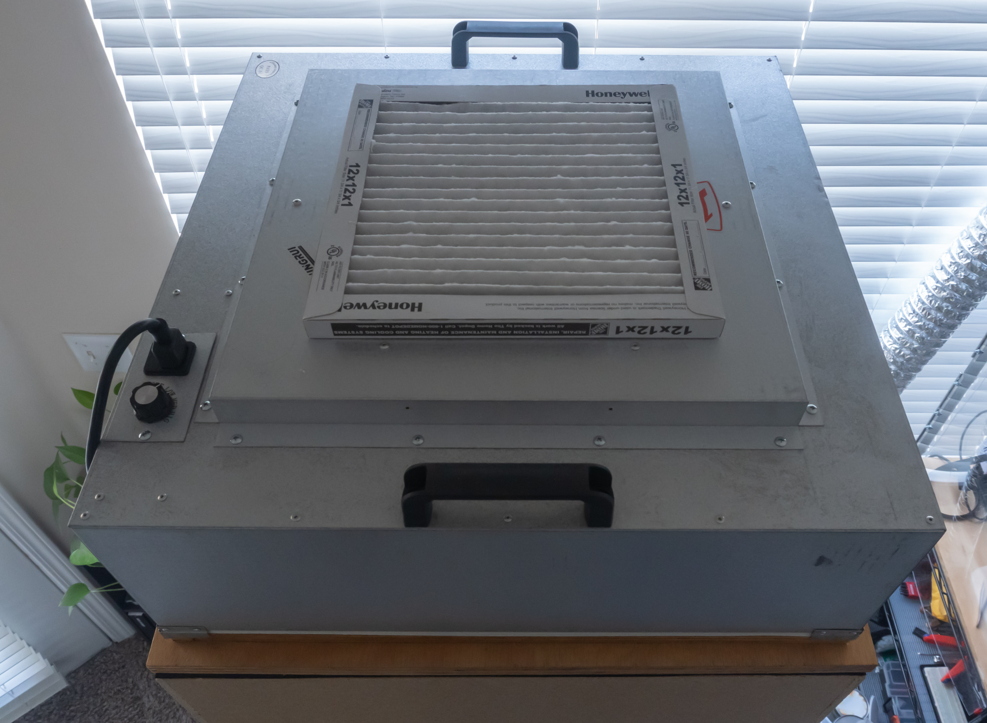
Additionally, you can extend the life of your HEPA filter by installing a coarse filter on the fan to filter larger particles. I found a 12 x 12 x 1 inch filter fit perfectly over the opening of my fan box opening.
Operation
The airflow should be just enough to provide a steady flow of air out of the opening of the hood. The fan I’m using has three speeds, however I found the lowest speed still produced too much air flow. Therefore, I installed a variable transformer, or variac, to reduce the voltage to the fan, and thus further slowed the speed.
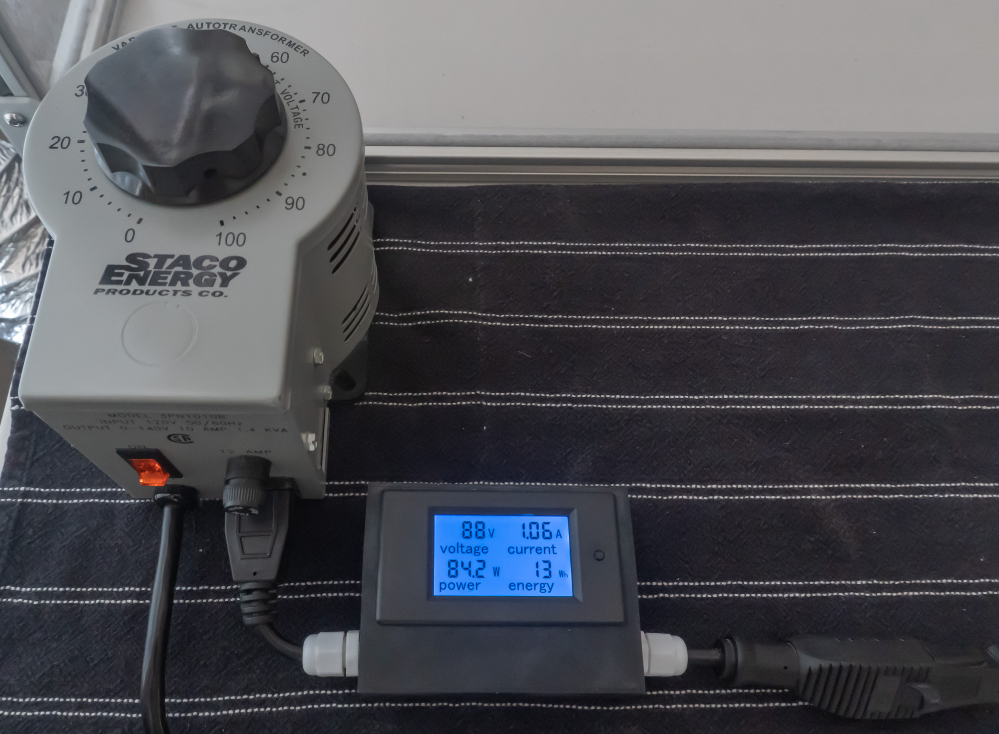
I know there will be many who will mention that a variable-frequency drive is what should be used for a brushless motor such as this and a variac can potentially damage the motor by allowing the motor to slip and draw too much current. However, I already had a variac and since it has an output outlet, it required no rewiring. I found ~90 volts AC (normally 120) produced an ideal fan speed, and at that voltage, I measured no increased current consumption with an in-line power meter I constructed. Furthermore, as this is a fan, the air flow over the motor is more than adequate to remove any additional heat that may be generated from any inefficiencies introduced.
Alternatively, you can achieve a slower air flow by simply using a shim to introduce a small opening between the fan and HEPA filter to allow some air to escape, effectively lowering the air pressure, resulting in less air passing through the filter and a lower air flow in the hood.
Building a Regulated Mushroom Cultivation Environment
Next, we’ll construct a simple humidity- and carbon dioxide-regulated chamber for colonizing and fruiting mushrooms. I will not include temperature regulation since this chamber is inside my temperature-regulated house, but this may be required if your ambient temperature is too high for what you would like to grow. I will also go over how I set up the lighting and automated time-lapse photography inside the chamber.
Control Panel

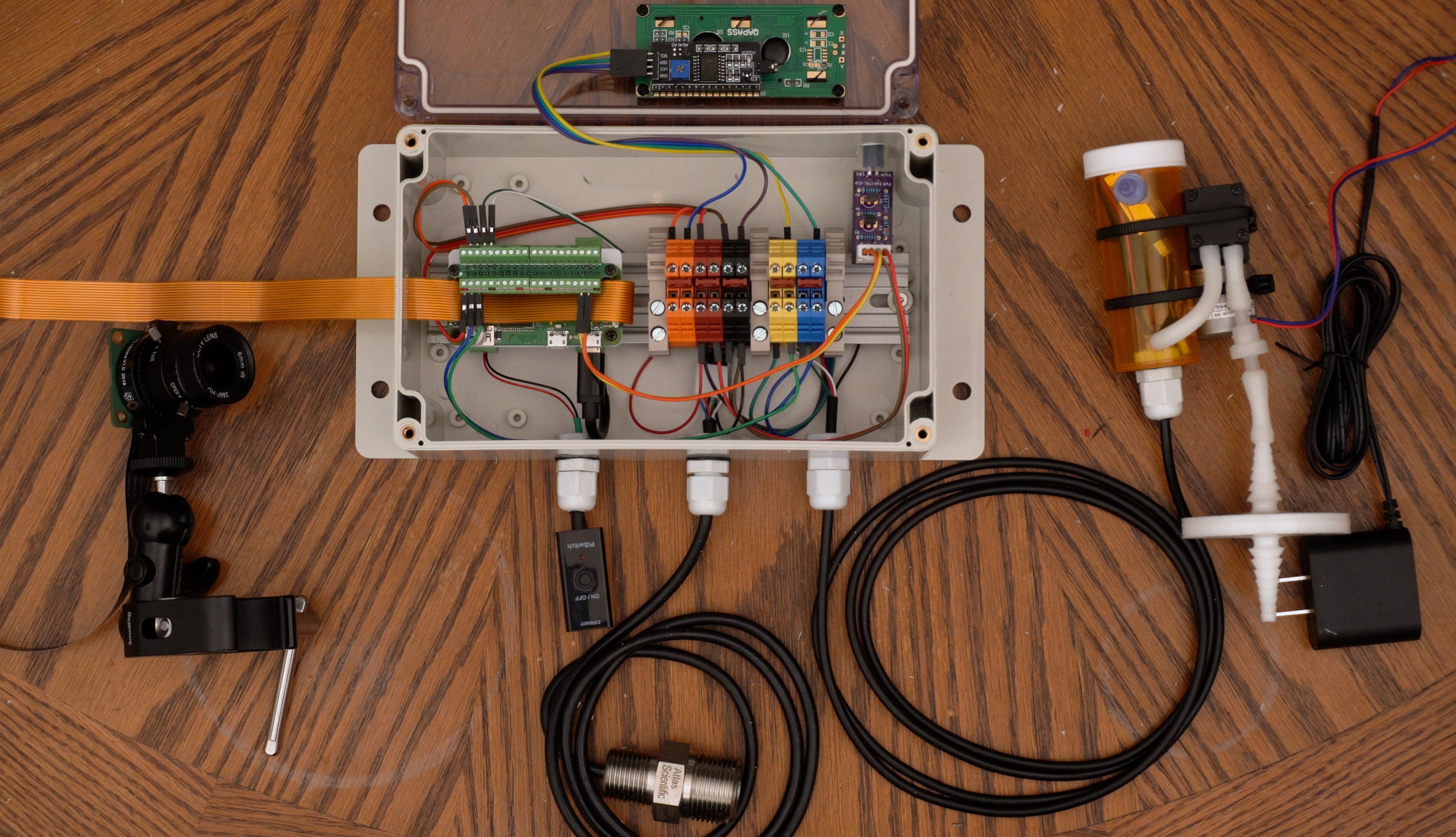
The control panel will house a Raspberry Pi Zero single board computer, which will interface all the inputs and outputs and orchestrate the environmental control. The temperature and humidity sensor as well as the carbon dioxide sensor will be connected as inputs. A small air pump will be connected to periodically draw air samples from the chamber for the carbon dioxide sensor to measure. A fan speed controller board will be connected to the electrically controlled duct fan and be used to exhaust carbon dioxide and introduce fresh air. An LCD will be affixed to the front on the panel for easy viewing of the current temperature, humidity, carbon dioxide concentration, and other data. Last, a light and a 12.3-megapixel High Quality Raspberry Pi Camera with a 6 mm lens will be connected to conduct time-lapse photography as well as monitor inside the chamber.

The DIN rail is affixed centrally in the back of the control panel and will hold the Raspberry Pi Zero as well as several terminal blocks.
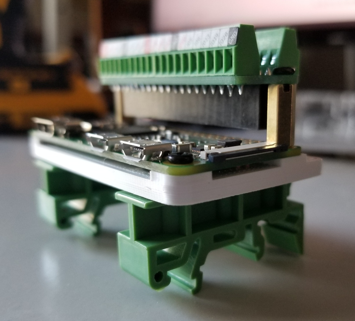
The Pi will need a male 40-pin header soldered to the header pin holes. The Pi is mounted with a custom Pi mount I designed and 3D printed, along with two DIN rail mounting adapters. The adapters are screwed in to the Pi mount, then the Pi is screwed on to the Pi mount using the standoff bolts that are included with the Pi terminal breakout module. Last, this Pi terminal breakout module is connected to the Pi header and screwed to the standoff bolts. Two more bolts can secure the remaining two Pi mounting holes to the 3D printed mount, but this isn’t necessary. This entire assembly can now be attached to the DIN rail in the control panel.
Ten terminal blocks were used in total, with two terminal blocks each connected to the Pi’s 3.3 volt, 5 volt, Ground, SDA, and SCL pins. End covers were used to separate the power terminal blocks from the SDA/SCL terminal blocks and used on the ends to secure the terminal blocks from moving or allowing anything to touch exposed contacts. Each pin from the Pi is connected to one of each terminal block set and terminal block jumpers were used to join each terminal block set. This breaks out the pins of the Pi to multiple terminal blocks and allows multiple wires to be connected.
The Atlas Scientific Temperature/Humidity Sensor is by default set to operate via a UART communication mode, but for this tutorial it will need to be changed to I2C mode following the instructions in the datasheet. Briefly, disconnect ground (power off), connect TX to INT, connect VCC to 3.3 volt, connect ground (power on), wait for the LED to change from Green to Blue, then disconnect ground (power off). The sensor should now be in I2C mode and you can disconnect INT and connect the SDA and SCL pins of the sensor cable to the SDA and SCL terminal blocks, respectively. Connect VCC of the sensor to a 3.3-volt terminal block and connect GND of the sensor to a Ground terminal block.
The MH-Z19B carbon dioxide sensor will connect to the Serial interface by connecting the Pi’s TX (transmit) and RX (receive) to the sensor’s RX and TX, respectively. Note that TX connects to RX and RX connects to TX of each device (TX does not connect to TX, nor does RX connect to RX), in order to allow communication in each direction. Connect the Vin of the sensor to a 5-volt terminal block and GND of the sensor to a Ground terminal block.
The LCD requires 5 volts to operate, so connect VCC of the LCD to a 5-volt terminal block. Connect GND of the LCD to a Ground terminal block. Then connect SDA and SCL of the LCD to the SDA and SCL terminal blocks, respectively. In this case, it’s okay to connect both 3.3 volt and 5 volt devices to the same I2C bus, so long as there are no pull-up resistors on the LCD pulling the bus to 5 volts (which there shouldn’t be). This works because I2C operates in an open-drain mode, where communication occurs from signals being pulled low (0 volts) rather than pulled high (3.3 or 5 volts). Devices on the same bus will all pull low, regardless of what their high voltage is.
The fan speed control board was soldered and placed near the top right of the panel to reduce the risk of the wire being pulled out of the socket. The PWM control wire of the board was connected to the GPIO 26 pin of the Pi, the power pin of the board to the 3.3 volt terminal block, and the ground pin of the board to the ground terminal block.
The camera ribbon cable for the Pi Zero is a special cable that is smaller than the typical ribbon cable of a full-size Raspberry Pi. Unfortunately, it seems only short cables are produced in this size, so a ribbon cable adapter is used to connect the small, short ribbon cable to a full-size, long ribbon cable, which provides a ribbon cable to allow the camera a sufficient length to be placed within the growth chamber. Once the ribbon cables are connected, connect the smaller ribbon cable to the Pi and the larger ribbon cable to the camera. A slit can be cut into the control panel to feed the ribbon cable in, as merely tightening the panel lid over the ribbon cable can cause damage to the cable.
All wires entering the control panel used cable glands to relieve any strain from the wires hanging. Power to the Pi was made with a micro USB power switch that was cut to allow it to feed through a cable gland, then soldered back together. It was then connected to the Pi Zero’s power micro USB connector and a power supply was connected to the power switch on the outside of the control panel.
Power Control
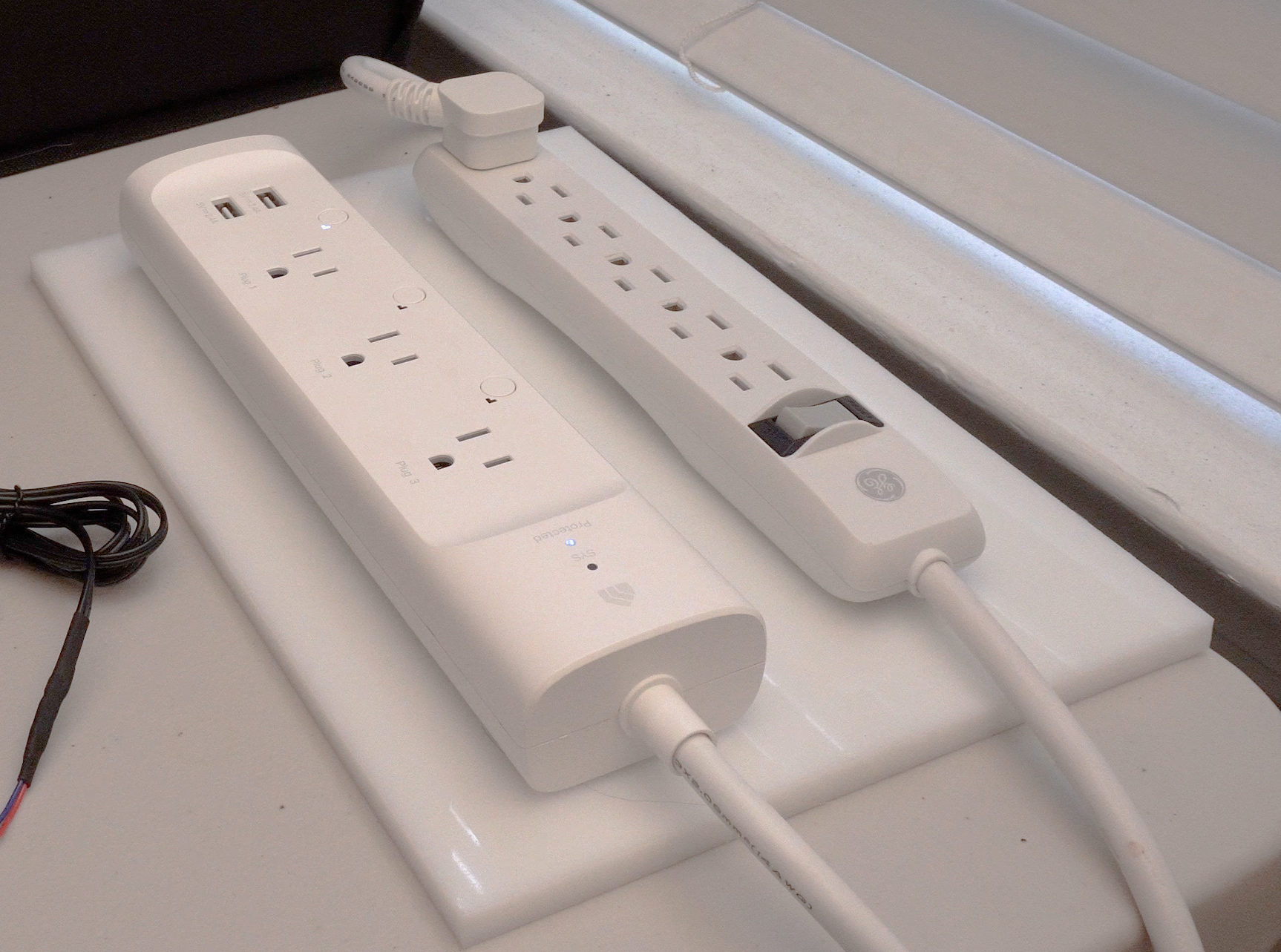
The power control box will allow the Raspberry Pi to safely switch high voltage electrical devices on and off. What I will be controlling is a humidifier, an air pump to sample air to measure carbon dioxide, and a light for time-lapse photography. I will be using a Kasa KP303 3-outlet WiFi power strip (see the Materials List), but there are many other WiFi-enabled power strips and outlets available to choose from. Followed the manufacturer’s instructions for connecting the WiFi power strip to your network.
Alternatively, you can build your own power control box like I’ve done in the past (see the Power Control Box section of my Automated Hydroponic System Build article).
Additionally, I will be using a single EFun SH331 WiFi power outlet (which has been discontinued) flashed with the Tasmota firmware. Tasmota is an amazing firmware that can be flashed to many wireless devices to give you more control options that they are normally shipped from the factory with. In addition to being able to control power to a device, this particular WiFi outlet also has the ability to measure power usage of whatever is connected to it. Therefore, instead of using it to control power, I will connect the power strip that the whole system is connected to in order to monitor and record the power usage of the system. There are many of these outlets on the market, however they are constantly being produced and discontinued, which is why at the time of writing this article, my EFun SH331 outlets are no longer available. It is recommended you review the list of Tasmota-supported devices to find one that is currently available.
Tent and Environmental Control
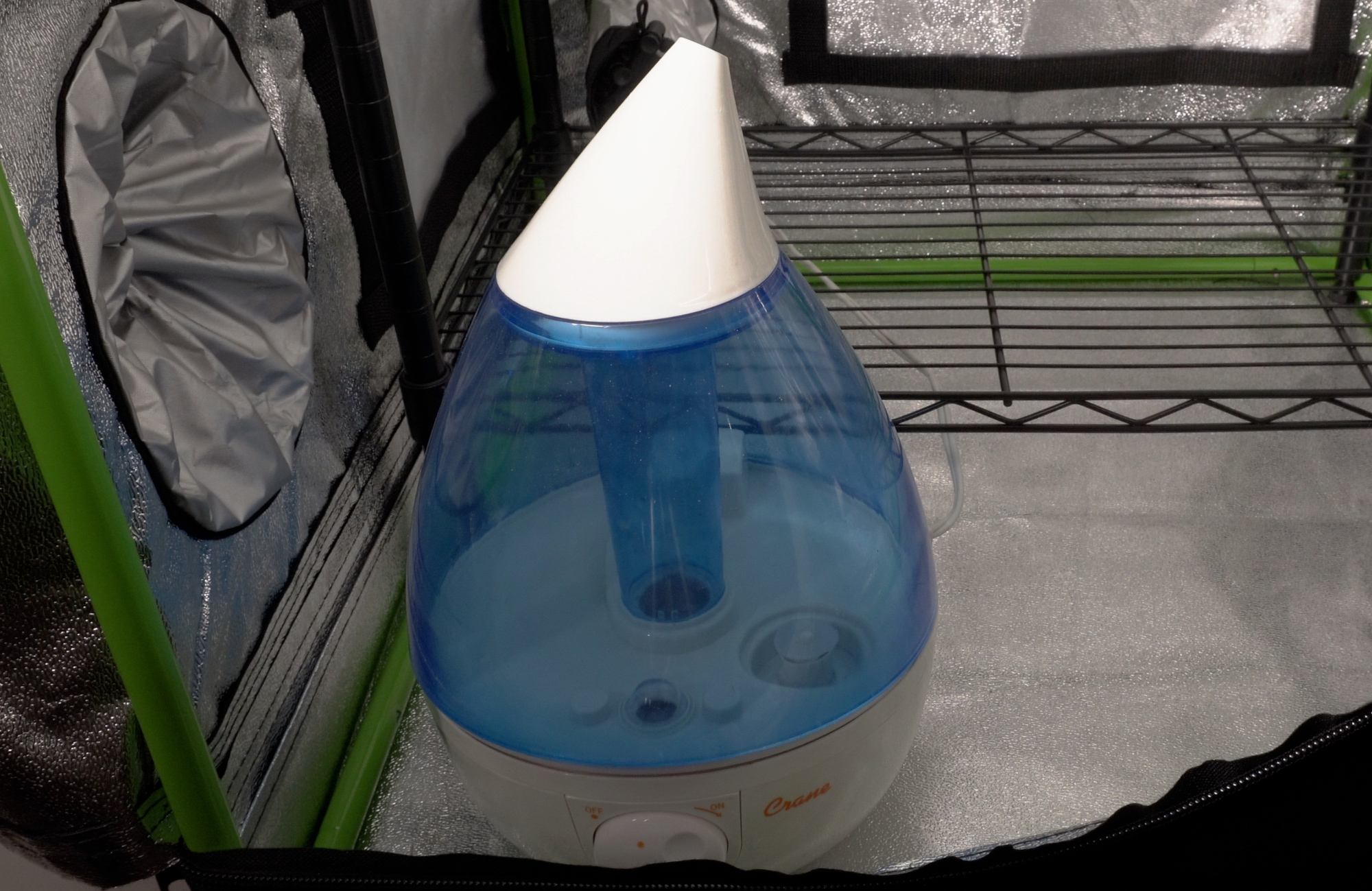
I’m using a 2 x 2 x 3 foot grow tent for my environmental chamber, which is excellent for retaining humidity and is light-tight, which prevents seeing lights turn on every 10 minutes during the time-lapse photography. Other enclosures may also work well, but the main consideration should be the ability to retain humidity in order to maintain adequate humidity and reduce the amount of water the humidifier uses.

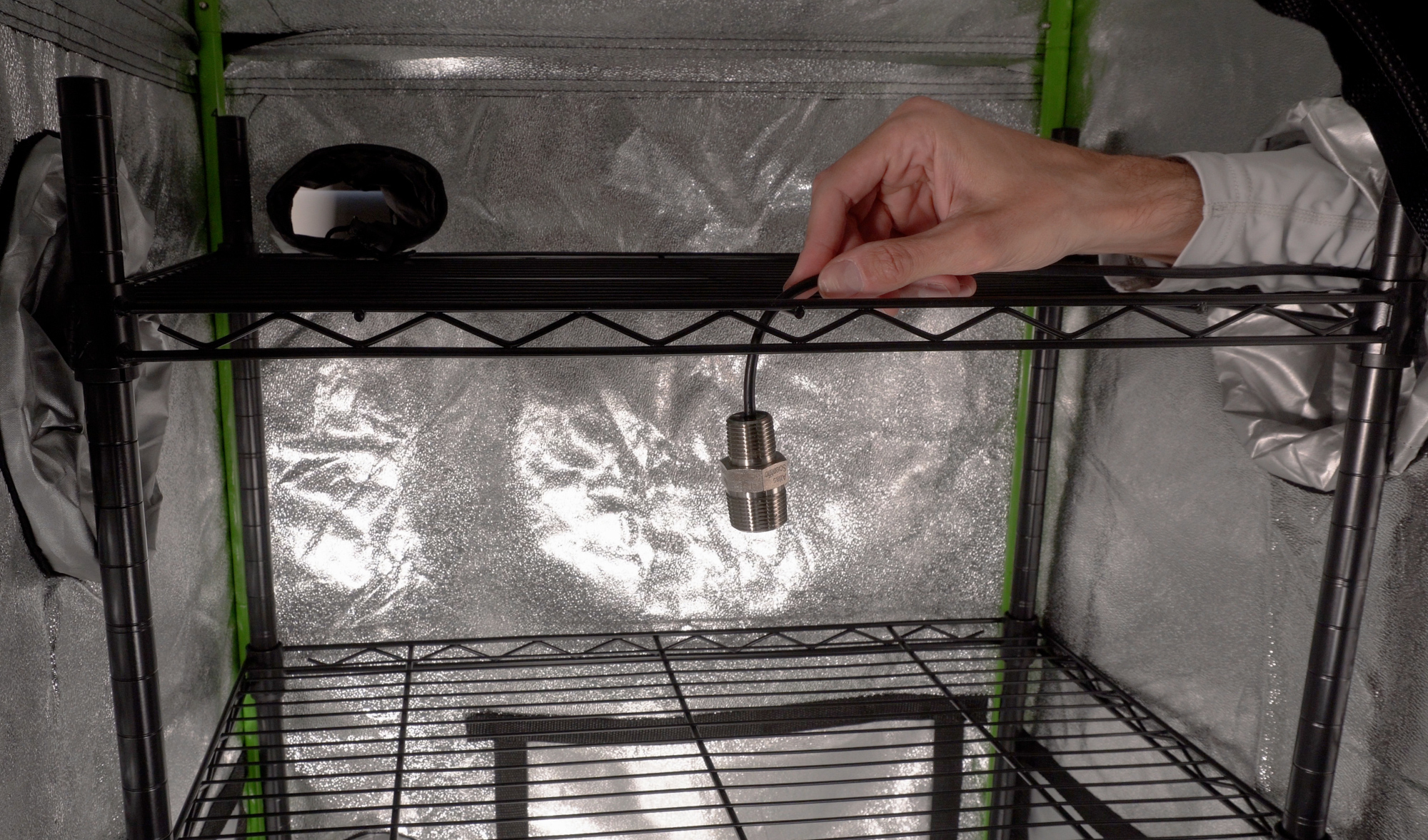
For sensing, I’m using an Atlas Scientific temperature and humidity sensor (HTU21D-F) and an MH-Z19B carbon dioxide sensor. I placed the temperature/humidity sensor near the center of the chamber, but it can be placed anywhere if using a circulation fan (recommended) to homogenize temperature and humidity within the chamber.
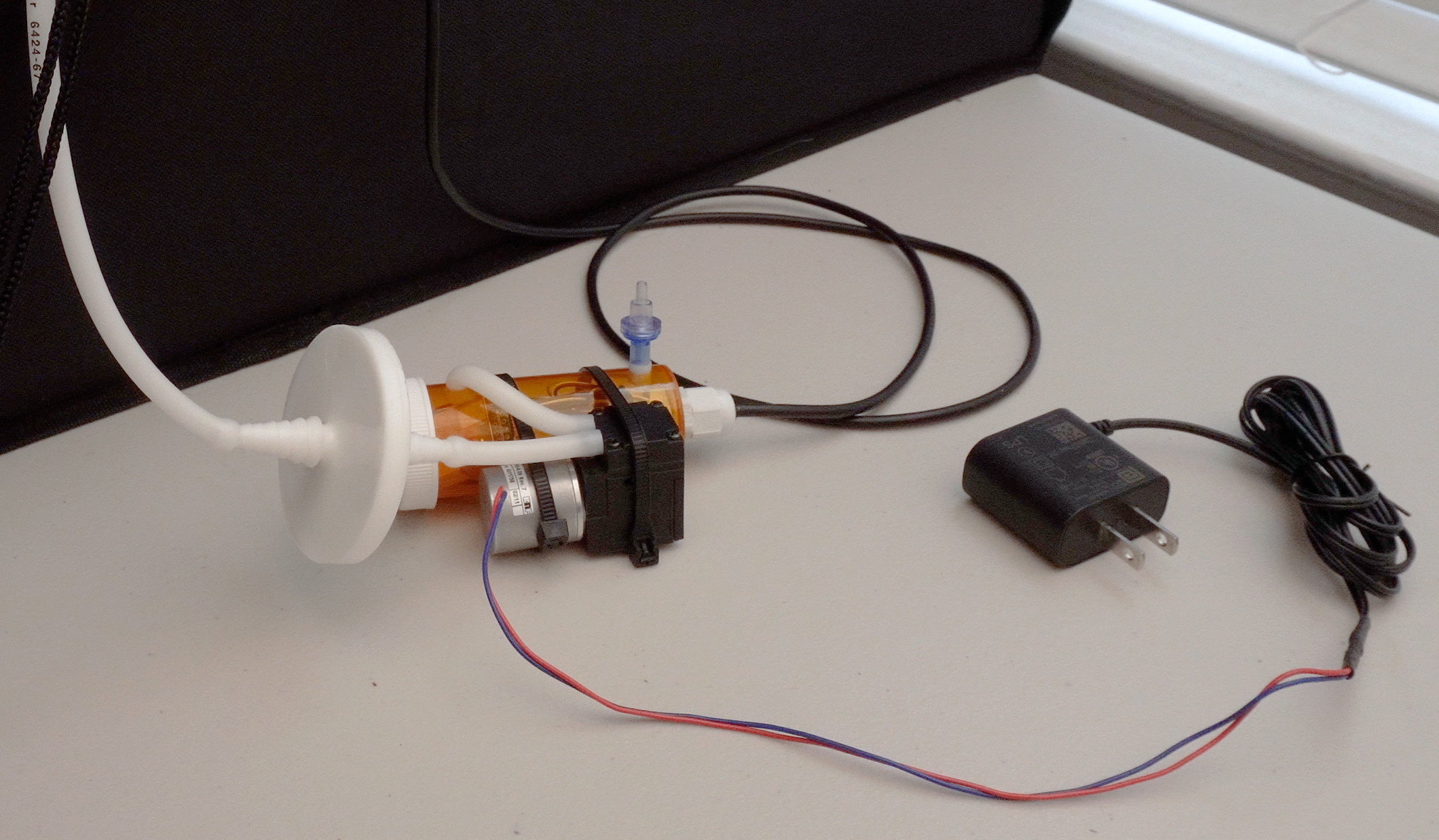
I chose to keep my carbon dioxide sensor outside the chamber and use a small diaphragm pump to draw air into a small sampling chamber for analysis by the sensor, but you could just place the sensor within the chamber. A 1-way check valve is fitted to the sampling chamber to only allow air to enter from the pump.
The other output devices include a humidifier, a light for time-lapse photography, and a speed-controlled fan for introducing fresh air into the chamber.

The humidifier, air pump, and light are connected to the wifi power strip. The circulation fan is connected to an always-on outlet and will run continuously. The speed controlled fan is connected to an always on power outlet and the control wire is connected to the speed controller board of the control panel. Last, an air filter is connected to the inlet of the fan.
Software Setup
Install Raspberry Pi OS
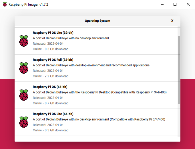
Raspberry Pi OS is the operating system that is developed by the Raspberry Pi Foundation (RPF) to run with the highest compatibility with Raspberry Pis. The RPF created a piece of software called the Raspberry Pi Imager that makes installing the Raspberry Pi OS to an SD card (or other storage device) very easy. Download the imager at https://www.raspberrypi.org/software, insert your SD card into your computer or an SD card reader, then run the Raspberry Pi Imager.
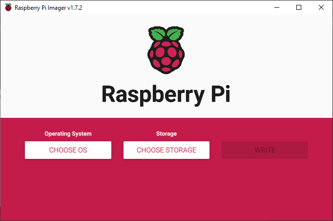
Select CHOOSE OS and select “Raspberry Pi OS (other)”, then choose “Raspberry Pi OS Lite (32-bit)” or “Raspberry Pi OS Lite (64-bit)” (if running a 64-bit Raspberry Pi). This version is small in size because it doesn’t include a graphical interface, as I will be instructing how to access the Pi headlessly (no monitor, keyboard, or mouse attached). If you want to attach these peripherals to your Pi and use it with a graphical desktop, you can select “Raspberry Pi OS Full (32-bit)” or “Raspberry Pi OS Full (64-bit)” (if running a 64-bit Raspberry Pi).
Select CHOOSE STORAGE and select your SD card that you inserted into your computer.
WARNING: Make sure you select the correct device, as installing the operating system will erase everything on the device you select.
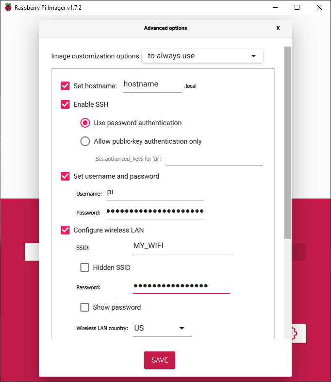
Next, press the gear icon to access the advanced options of the Raspberry Pi Imager. Check the Enable SSH option and enter a Username and Password. Check the Configure Wireless LAN (WiFi) option, enter your WiFi SSID, WiFi Password, and select your WiFi Country. Check the Set Locale Settings option and select your Time Zone and Keyboard Layout. Press Save, then press Write to begin writing the operating system to your SD card.
When the OS has been successfully written to your SD card, you can eject the card and insert it into your Pi. Power on your Pi and give it a few minutes to boot up for the first time, which will involve expanding a partition on the SD card. This will only happen during the first boot and subsequent boots will be slightly faster. You can then log in to your router to see when the Pi is connected and discover what IP address is has been assigned. Alternatively, you can use a tool such as Fing (Android) to scan your network for the Pi. If you installed the Full OS, you can use the mouse and keyboard connected to the Pi to log in, open a terminal, and issue the command “ifconfig” and look for the “inet” line under the device “wlan0”, which will show you the Pi’s WiFi IP address. If using a full-size Pi, you could connect the Pi via an ethernet cable to your network and the IP address will be under the “eth0” device after issuing the “ifconfig” command. You can also use the software Advanced IP Scanner (windows) or from mac/linux you can run the “arp” command:
arp -a | grep raspberryWhich should output something similar to this if it finds a Raspberry Pi on the network:
raspberrypi.home (192.168.0.10) at b3:27:eb:2a:40:c0 [ether] on wlxc8d7193bf721Install Mycodo
Once you have the Raspberry Pi OS installed and have the IP address of your Pi on your network, you can install the Mycodo environmental regulation software on the Pi. We will be connecting to the Pi headlessly with the remote terminal program PuTTY. Alternatively, if you have a monitor, keyboard, and mouse connected to your Pi, you can run the following commands in a virtual terminal on the desktop rather than through PuTTY.
If using Windows, install PuTTY, run it, and connect to the host “pi@192.168.0.10”, changing the IP address to that of your Raspberry Pi. If using Mac, open a terminal and type “ssh pi@192.168.0.10”. In either case, you should be presented with a window to accept the SSH key, then a password prompt. Enter the password you set earlier in the Raspberry Pi OS Imager, and you should then be logged in remotely to your Pi with a terminal in front of you.
At the terminal, run the following commands to update your operating system packages:
sudo apt update
sudo apt upgrade
Enter your password when prompted and select Yes to install any packages that there are updates for. When the update and upgrade finishes, run the command “sudo raspi-config” to open the Raspberry Pi Config menu. Navigate to the “Interface Options” menu. Select and enable I2C. Select Serial Port, then choose No when asked “Would you like a login shell to be accessible over serial?”, and choose Yes when asked “Would you like the serial port hardware to be enabled?”. If you will be using a Raspberry Pi Camera, select and enable it with the Camera option. Last, select Back, then Finish. You will be prompted to reboot the system, which is necessary to load your new configuration, so select Yes and let the Pi reboot.
Once the Pi has rebooted and you’ve logged back in, we’re ready to install Mycodo. Visit the Install section of the Mycodo GitHub page for the latest instructions and commands to install Mycodo, as they may have changed since this article was written. However, as of the writing of this article, it is the following command:
curl -L https://kizniche.github.io/Mycodo/install | bashYou will be prompted to acknowledge the software license and that it will make changes to your system during the install process. Select Yes to both prompts and Mycodo will begin installing. Depending on which Raspberry Pi model you are installing to and how powerful it is, it can take anywhere from 5 minutes (Pi 4) to 30 minutes or longer (Pi Zero) to install. At the end of the installation, you will be presented with a web address that you can access the Mycodo Web Interface, such as https://192.168.0.10. Make sure the IP address is the IP address of your Pi. Open a web browser on a computer, tablet, or phone connected to the same network as your Pi, or in a browser on the desktop of your Pi, and navigate to the web address. The first time you load the home page, you will be prompted to create an administrative user by supplying a username and password. Once you’ve created this user, you will be presented with a login prompt to login with the credentials you just created.
Configure Mycodo
Mycodo is designed to be easy for beginners to use, yet powerful once you’ve become familiar with it and begin utilizing its advanced features. Let’s go over how we’re going to set up this Mycodo system to communicate with our Inputs and Outputs and operate our environmental chamber for mushroom cultivation.
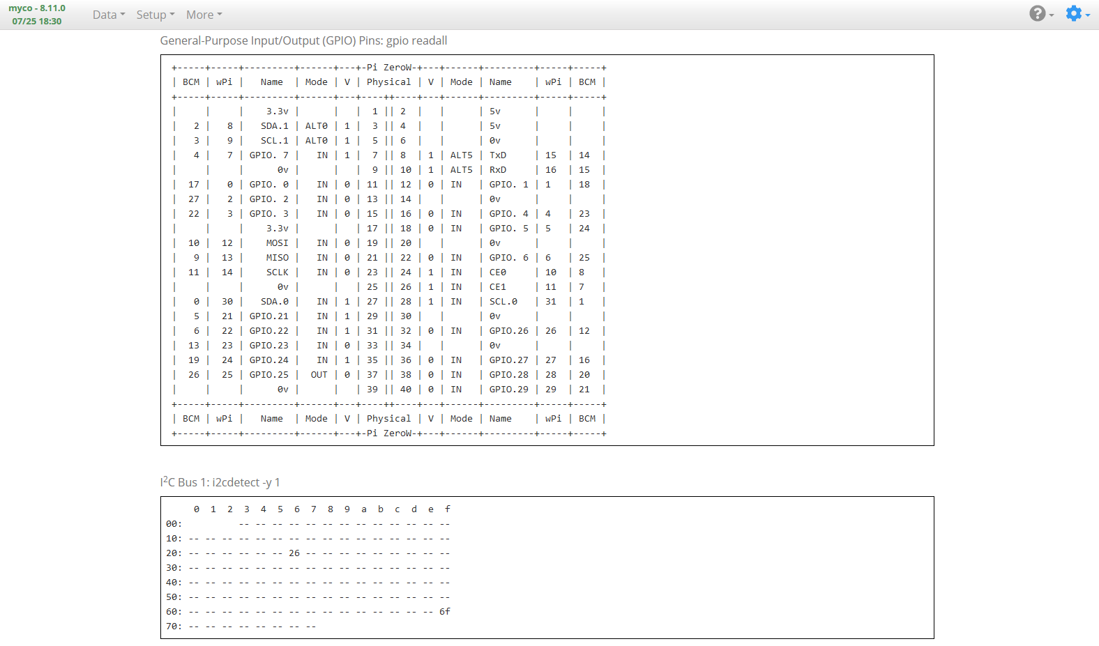
System Information Page
Input Page
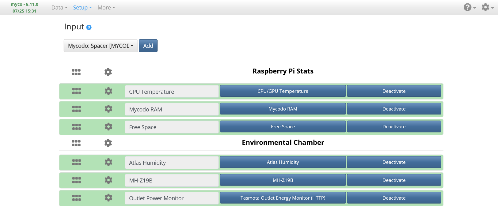
The Setup -> Input page is where input sources are added and configured.
Temperature and Humidity Sensor Input
Add the Atlas Scientific Temperature and Humidity Sensor Input (named Atlas Humidity, above). The default settings should work fine, so just Activate it.
Carbon Dioxide Sensor Input
Add a MH-Z19B Carbon Dioxide Sensor Input (named MH-Z19B, above) and set the UART Device to “/dev/ttyS0”, the Period to “1800”, the Pre Output to the CO2 Air Pump Output and the Pre Out Duration to “30” seconds (if using a pump to sample air), Save, then Activate.
Note: the CO2 Air Pump Output doesn’t exist yet, so once you’ve added it in the next section, come back to this Input and configure it.
Power Monitor Input
Add a Tasmota Outlet Energy Monitor Input (if applicable, named Outlet Power Monitor, above) and set the Outlet Energy Monitor’s Host to the IP address of your Tasmota outlet, Save, then Activate.
In the screenshot I have three additional Inputs to monitor my Raspberry Pi, but these aren’t necessary for the system to operate. If desired, search in the dropdown list for these Inputs to add and activate them.
Live Measurements Page
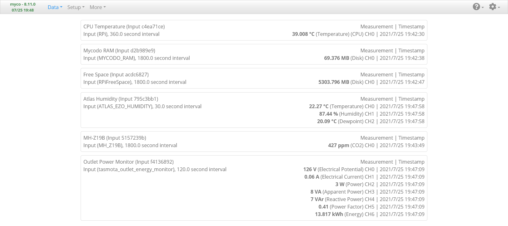
The Data -> Live Measurements page is where the most recent measurements from the Inputs are displayed. Once you’ve added, configured, and activated the Inputs, go there to the to see if you’re receiving measurements from your Inputs. If any Inputs are not returning measurements, review the setup procedures to make sure you’ve followed the instructions appropriately to set up your devices. You can go to the [Gear Icon] -> Mycodo Logs page and view the Daemon Log to see if there are any relevant errors that may help you determine the issue.
Output Page
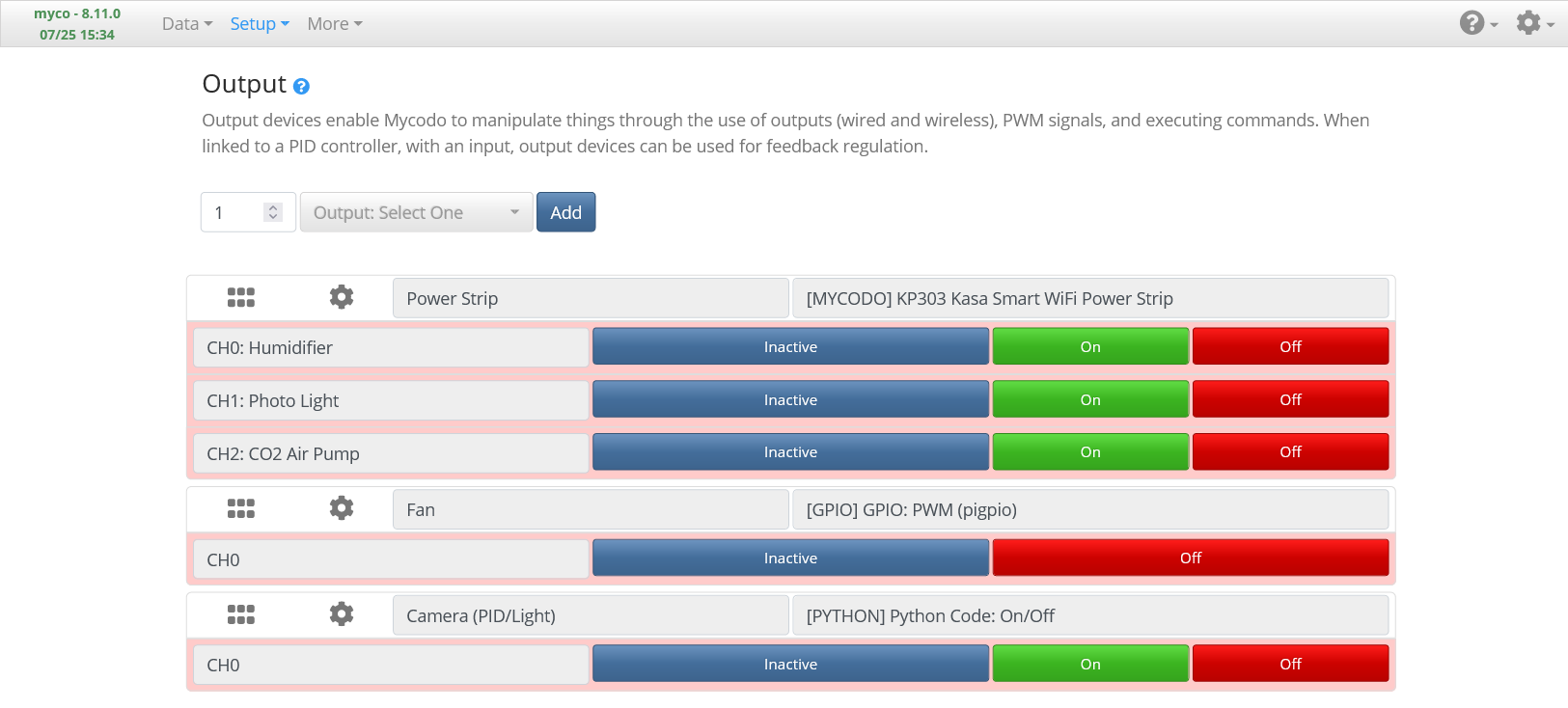
The Setup -> Output page is where output sources are added and configured.
WiFi Power Strip Output
Add the Kasa KP303 Output (named Power Strip, above), set the Host to the IP address of your wifi power strip, then press Save. Test that each outlet works by connecting a device and turning it on and off with the On/Off buttons on the Output Page. You can set the Channel names to the devices that will be connected to the power strip: Humidifier, CO2 Air Pump, and Photo Light (if applicable).
Fan Speed Control PWM Output
Add a GPIO PWM Output (named Fan, above) and set the GPIO Pin (using BCM numbering) to the pin you connected your Fan Control Board’s PWM Pin. Enter a Duty Cycle of 50, press Send, and verify the fan starts to spin. Enter a Duty Cycle of 0 and press Send to turn the fan off.
Photo Time-lapse Light Output
Last, if you’re using a light for photos, add a Python Code On/Off Output (named Camera (PID/Light), above), and set the On Command to:
PID_ID = "0785b59b-00dd-47f0-a5af-05f368f7a504"
POWER_STRIP_ID = "f3dda59d-8052-4dc8-87f1-124d286427ff"
control.pid_pause(PID_ID)  # Pause PID
control.output_off(POWER_STRIP_ID, output_channel=0)  # Humidifier Off
control.output_on(POWER_STRIP_ID, output_channel=1)  # Light On
And the Off Command to:
PID_ID = "0785b59b-00dd-47f0-a5af-05f368f7a504"
POWER_STRIP_ID = "f3dda59d-8052-4dc8-87f1-124d286427ff"
control.output_off(POWER_STRIP_ID, output_channel=1)  # Light Off
control.pid_resume(PID_ID)  # PID Resume
You will need to change the IDs to your actual PID Controller Function (set up in the next section) and Power Strip Output IDs. These can be found by hovering your mouse over the title of the controller. You can press the button you’re hovering your mouse over to easily copy the ID to your clipboard. Also ensure your Power Strip Output channels are correct. In the example code, the Humidifier is Channel 0 and the Light is Channel 1, but this might not be the same as how you set your Output up. This output will pause the PID, turn off the humidifier, and turn on the light. This ensures there isn’t fog obscuring the photo from the humidifier being active. When we configure the camera, we will set this Output to be activated for a duration of 60 seconds, giving a sufficient amount of time before the photo is taken for any fog to dissipate.
Settings: Alert Page
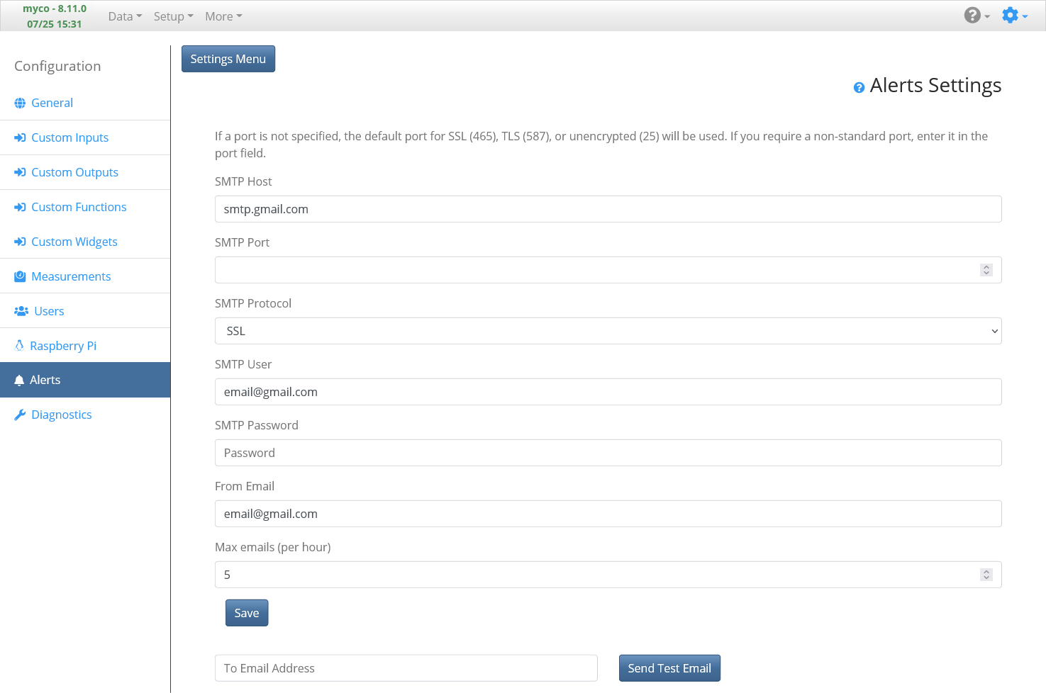
Before we set up the Functions, let’s set up the ability for the system to send emails. We’ll use this functionality next to set up a Function to send notifications if measurements fall outside set ranges, indicating there may be an issue with our system. I typically use Gmail to send alert emails and I recommend creating a new account just for this. To set up Alerts to use Gmail, set SMTP Host to “smtp.gmail.com”, SMTP Protocol to “SSL”, and SMTP User and From Email to your full Gmail email address. Last, enter the email address password in the SMTP Password field. Additionally, you can change how many emails that allowed to be sent per hour. Use the Send Test Email field and button to send a test email. If the email doesn’t get delivered, you will likely need to enable Less Secure Apps in your google account security settings (see below).

In the future, there will be more notification options added to Mycodo, such as Discord, Slack, SMS, Twitter, and other methods.
Function Page
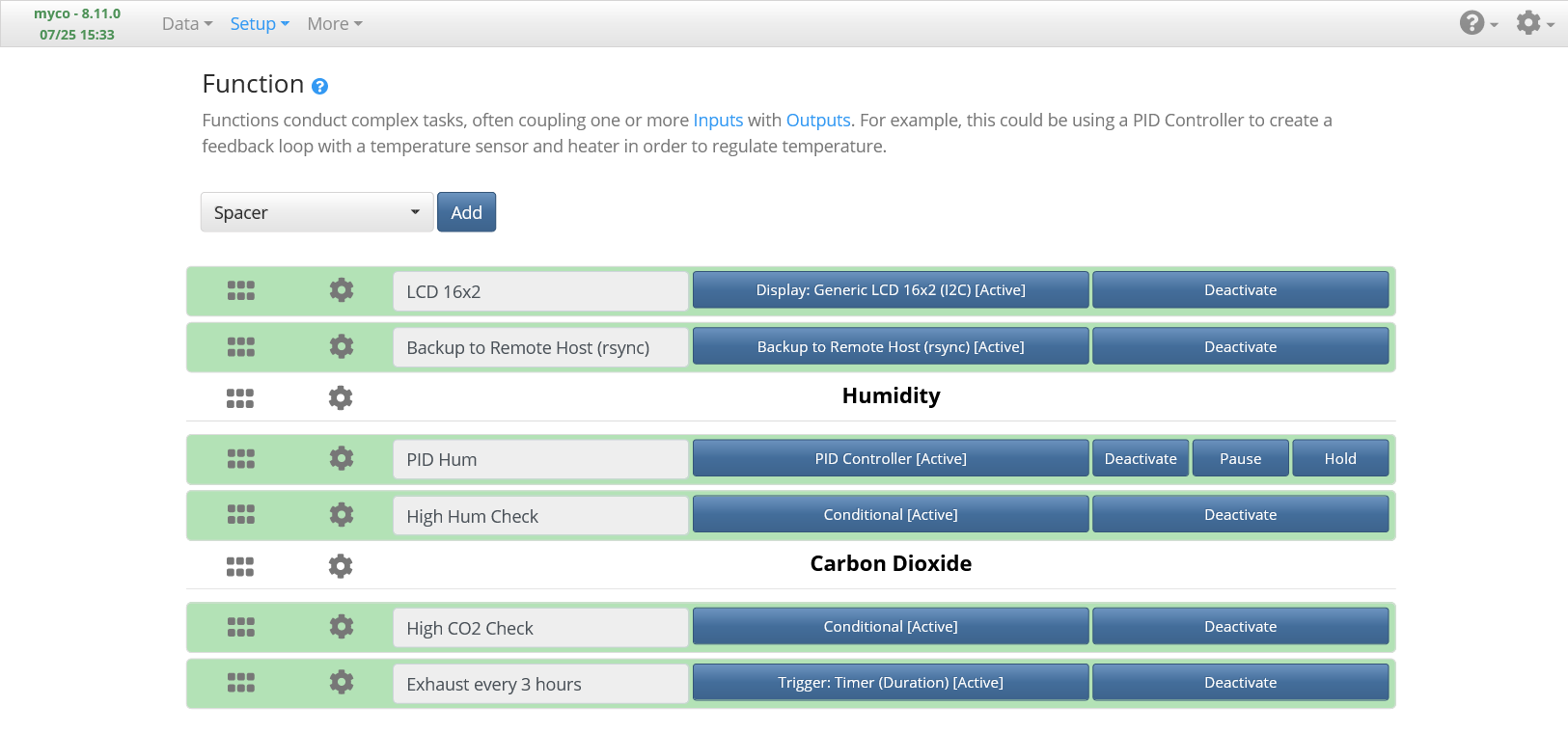
The Setup -> Function page is where Functions will be added and configured, which will allow you to program things as simple as duration timers or as complex as custom code to query Input measurements and control Output devices. There are a number of pre-defined Functions to choose from or you can create and import your own.
LCD Display Function
Add a Generic 16×2 LCD Function (named LCD 16×2, above), set the I2C Address to the address of the LCD (found in the I2C device tree on the System Information page). Set as many display sets as you want and set the display lines to whichever data you want to display, such as Temperature, Humidity, Raspberry Pi IP address, Custom Text, etc., then Activate it.
Humidity Regulation PID Function
Add a PID Controller Function (named PID Humidity, above). Set the Measurement to the Humidity measurement of the input set up earlier, Period to “120” seconds, Setpoint to “85” percent humidity, Kp Gain to “3.0”, Ki Gain to “0.25”, Kd Gain to “0”, Raise Output to the Humidifier Output, Raise Min On Duration to “15” seconds, and Raise Min Off Duration to “20” seconds. These settings may need to be tuned for your particular humidifier + tent system, but if you set your humidifier to the lowest output, these should work well if using a small environment such as the one I’m using. Save, and Activate. Monitor the humidity on the Live Measurements page and make sure your humidifier begins turning on periodically.
Note: you will want to ensure your environmental chamber is completely sealed at this point for the humidity to be able to rise to the setpoint of 85 %. Any breach of the chamber will allow humidity to escape, possibly resulting in it being difficult or impossible for the system to attain the desired humidity.
Carbon Dioxide Regulation Function
Add a Conditional Controller Function (named High Hum Check, above). Set the Period to “90” seconds. Add a “Measurement (Single, Last)” Condition and set it to the Humidity measurement. Add an “Output (Duty Cycle)” Action, set it to the Fan PWM Output, and a Duty Cycle of “30” percent. Add a “Pause” Action and set it to “10” seconds. Add an “Output (Duty Cycle)” Action, set it to the Fan PWM Output, and a Duty Cycle of “0” percent. The order of the Actions is important, so make sure you add then in the order listed. Set the Conditional Statement to:
measurement = self.condition("{4619f4a1}")
if measurement is not None:
    if measurement > 98:
        self.run_all_actions()
Be sure to change the ID of the Condition to the ID that’s specified in your Function settings, below the Condition. Press Save, then Activate. This Conditional Controller will check the humidity every 90 seconds and if the humidity is higher than 98 %, it will exhaust air for 10 seconds. This ensures any issues that may arise from the Humidity PID controller or elsewhere (e.g. the humidifier being unable to turn off) won’t allow the chamber to become too humid.
Depending if you’re using a camera light or not, you will use one of the following, either A or B:
A: If using a camera light, add a Conditional Controller Function (named High CO2 Check, above). Set the Period to “60” seconds. Add a “Measurement (Single, Last)” Condition and set it to the CO2 Measurement. Add an “Output State” Condition and set it to the Light Output. Add an “Output (Duty Cycle)” Action, set it to the Fan Output, and the Duty Cycle to “0” percent (Fan off). Add an “Output (Duty Cycle)” Action, set it to the Fan Output, and the Duty Cycle to “100” percent (Fan on). Add an “Output (On/Off/Duration)” Action, set it to the Humidifier, the State to “On”, and the Duration to “90” seconds. Set the Conditional Statement to:
co2_limit = 700
on_duration = 90
run_interval = 1900

import time
measurement = self.condition("{b719d47a}")  # CO2 Measurement

try:
    print(self.last_on)
except:
    self.last_on = 0
    self.stay_off_until = 0
    self.turned_off = True

if self.last_on + on_duration < time.time() and not self.turned_off:
    self.run_action("{18a86305}")  # Fan off
    self.turned_off = True

if measurement is not None:
    if time.time() > self.stay_off_until and measurement > co2_limit:
        self.logger.info("CO2 > {}: {} ppm".format(co2_limit, measurement))
        self.last_on = time.time()
        self.stay_off_until = time.time() + run_interval
        self.run_action("{9e6fac6d}")  # Fan on
        if self.condition("{64af1d29}") == "off":  # If the light is Off
            self.run_action("{5fa75b9a}")  # Humidifier on
            self.turned_off = False
Be sure to change the IDs to match those of your particular Conditions and Actions. This Conditional Controller will exhaust air if the CO2 Concentration rises above the set co2_limit (700 ppmv). If the Light is off, it will turn the humidifier on to counteract the non-humid air being introduced into the chamber. However, if the light is on (indicating a photo is being taken), it will not turn the humidifier on, which would cause a potentially foggy photo to be taken. This function will only run every set run_interval (1900 seconds), since the CO2 sensor only runs every 1800 seconds. If this function were to run any sooner, it would potentially be using the same old CO2 measurement as the previous execution. Therefore, we must set the run time to be greater than the sensor measurement Period.
B: If not using a camera light, add a Conditional Controller Function (named High CO2 Check, above). Set the Period to “60” seconds. Add a “Measurement (Single, Last)” Condition and set it to the CO2 Measurement. Add an “Output (Duty Cycle)” Action, set it to the Fan Output, and the Duty Cycle to “0” percent. Add an “Output (Duty Cycle)” Action, set it to the Fan Output, and the Duty Cycle to “0” percent. Add an “Output (On/Off/Duration)” Action, set it to the Humidifier, the State to “On”, and the Duration to “90” seconds. Set the Conditional Statement to:
co2_limit = 700
on_duration = 90
run_interval = 1900

import time
measurement = self.condition("{b719d47a}")

try:
    print(self.last_on)
except:
    self.last_on = 0
    self.stay_off_until = 0
    self.turned_off = True

if self.last_on + on_duration < time.time() and not self.turned_off:
    self.run_action("{18a86305}")  # Turn off if has been on
    self.turned_off = True

if measurement is not None:
    if time.time() > self.stay_off_until and measurement > co2_limit:
        self.logger.info("CO2 > {}: {} ppm".format(co2_limit, measurement))
        self.last_on = time.time()
        self.stay_off_until = time.time() + run_interval
        self.run_action("{9e6fac6d}")  # Fan on
        self.run_action("{5fa75b9a}")  # Humidifier on
        self.turned_off = False
Be sure to change the IDs to match those of your particular Conditions and Actions. This Conditional Statement is very similar to the previous one, but with the Light Condition and the corresponding code to check the state of the light removed.
Low Humidity Email Alert Function
Finally, let’s create a Conditional that will alert by email if the humidity falls below 70 %, which could indicate an issue with the system or the humidifier is out of water. Add a Conditional Controller Function. Set the Period to “3600” seconds. Add a “Measurement (Single, Last)” Condition and set it to the Humidity measurement. Add an “Email (Single)” Action, set it to the email address you want to be notified. The email addresses in the dropdown selection are populated from the email addresses set in the User Configuration. Set the Conditional Statement to:
humidity_too_low = 70

humidity_measure = self.condition("{f8s300f7}")  # Latest humidity measurement
if humidity_measure and humidity_measure <= humidity_too_low:
    self.message += "Humidity is too low! Humidity is {} %".format(humidity_measure)
    self.run_action("{3uc6a03n}", message=self.message)  # Send email alert with current humidity
Camera Page
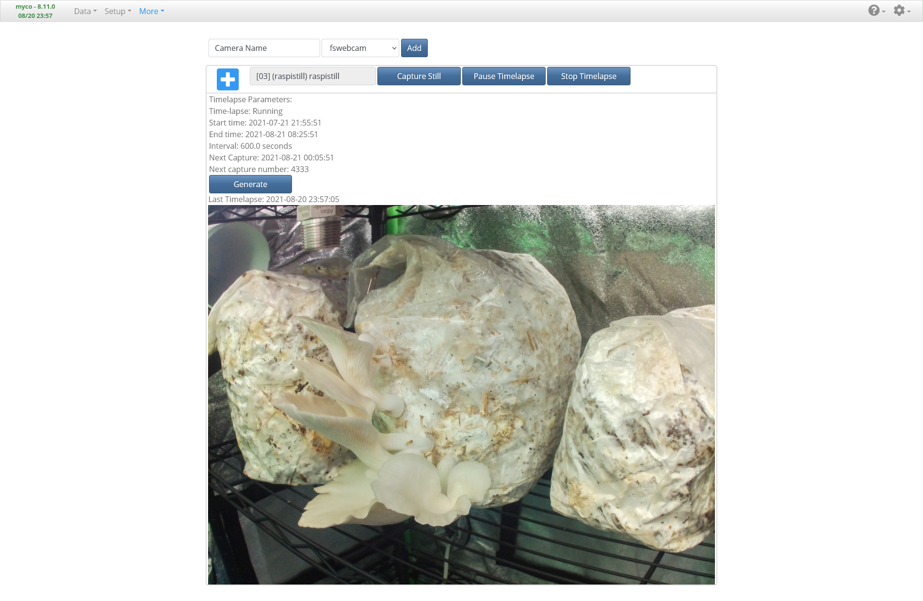
The More -> Camera page is where we can configure our Raspberry Pi Camera (or USB, IP, HTTP, etc. camera if you want to use any of those) to stream video, take photos, or conduct time-lapse photography. Since the inside of the chamber is pitch black, the light we set up earlier will be used to illuminate the inside while photos are being taken. Add a new camera with the Raspistill library selected. I prefer this library over the picamera library because it seems to be more reliable when taking photos at the highest resolution of the HQ Raspberry Pi Camera. In the camera configuration, set the Output to the Camera (PID/Light) Output, Duration (Output) to “60” seconds, and the Still Image Width and Height to the highest native resolution of your particular camera. For the HQ Raspberry Pi Camera, this is 4056 x 3040 pixels. Save, then press the Capture Still button. After 60 seconds, you should see a photo appear after the page refresh. If not, try reducing the resolution and try again. If a photo does appear but is black, check that the light turned on during the photo. If a photo was taken, it is highly recommended to turn off the camera library’s auto settings and use all manual settings, as auto white balance and auto ISO can create slight variations in each photo of a time-lapse and make the resulting video disorienting to watch as white balance and ISO constantly changes throughout the video. You may need to tweak these settings by small amounts at a time and take numerous photos in order to find the best combination. Once you’ve tuned the camera settings adequately, experiment with starting time-lapses and generating videos after you’ve created a sufficient number of photos.
Dashboard Page
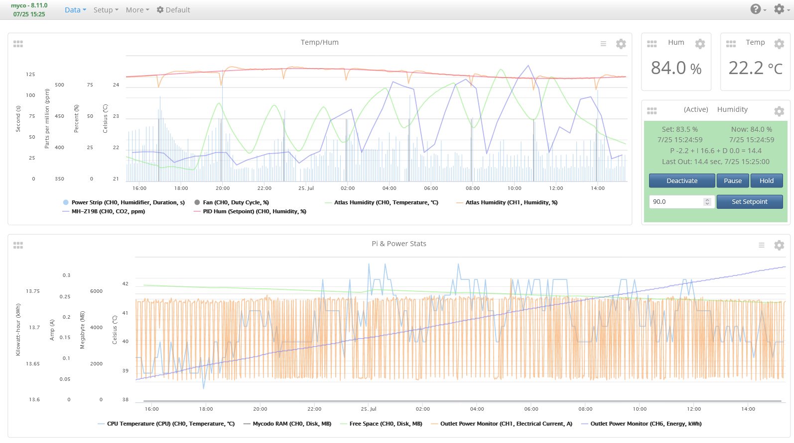
The Data -> Dashboard page is where you will add widgets to display information about the past and current conditions of the system. We will set up a simple dashboard with graphs displaying historical and live data as well as measurement widgets displaying the latest temperature and humidity measurements, as well as a PID control widget that will show the current parameters of the PID Controller and allow a minimal set of control options.
Add a Graph Widget, two Measurement Widgets, and one PID Widget. Set the Graph Widget to show Temperature, Humidity, and CO2. Set the Measurement Widgets to show Temperature and Humidity. Last, set the PID Widget to use the Humidity PID Controller. If you set any of the Inputs to record Pi statistics, you can create a second Graph and select these Inputs to be displayed.
This concludes the setup of the environmental chamber. There may be some tuning to get it to operate to your particular needs, especially if the development of your system deviated from these instructions. Run the system for several days or weeks to learn how it works, tweak the values of the configuration to get it to operate efficiently, and ensure it can perform reliably, prior to adding anything to grow in it.
Mushroom Cultivation
To effectively culture and fruit mushrooms, you must understand the mushroom life cycle. Mushroom-producing fungi typically begin their life as either spores or hypha (plural hyphae). Spores are small single-cell structures released from mushrooms (akin to seeds of a plant) and can often withstand harsh environments until conditions become hospitable, at which point hyphae grow from the spore. Hyphae are multicellular filamentous structures of the fungus that extend into the environment and are how the organism expands in size, moves through the environment, and acquires nutrients. Multiple hyphae are known as mycelium (plural mycelia), and these mycelia are what colonize substrates in order to extract nutrients to grow. Fungi excrete exoenzymes outside their cells that break down the substrates they’re colonizing into small-molecule nutrients, allowing easier transport into their cells. Because of this, fungi are significant decomposers of organic matter, with many mushroom species extremely effective at degrading lignocellulosic compounds, a principle component of plants. For this reason, many different plant-based materials can be used to grow mushrooms, such as agricultural wastes like peanut shells, corn cobs, straw, and more, as well as unconventional materials like cardboard and bluejeans.
Foraging Mushrooms
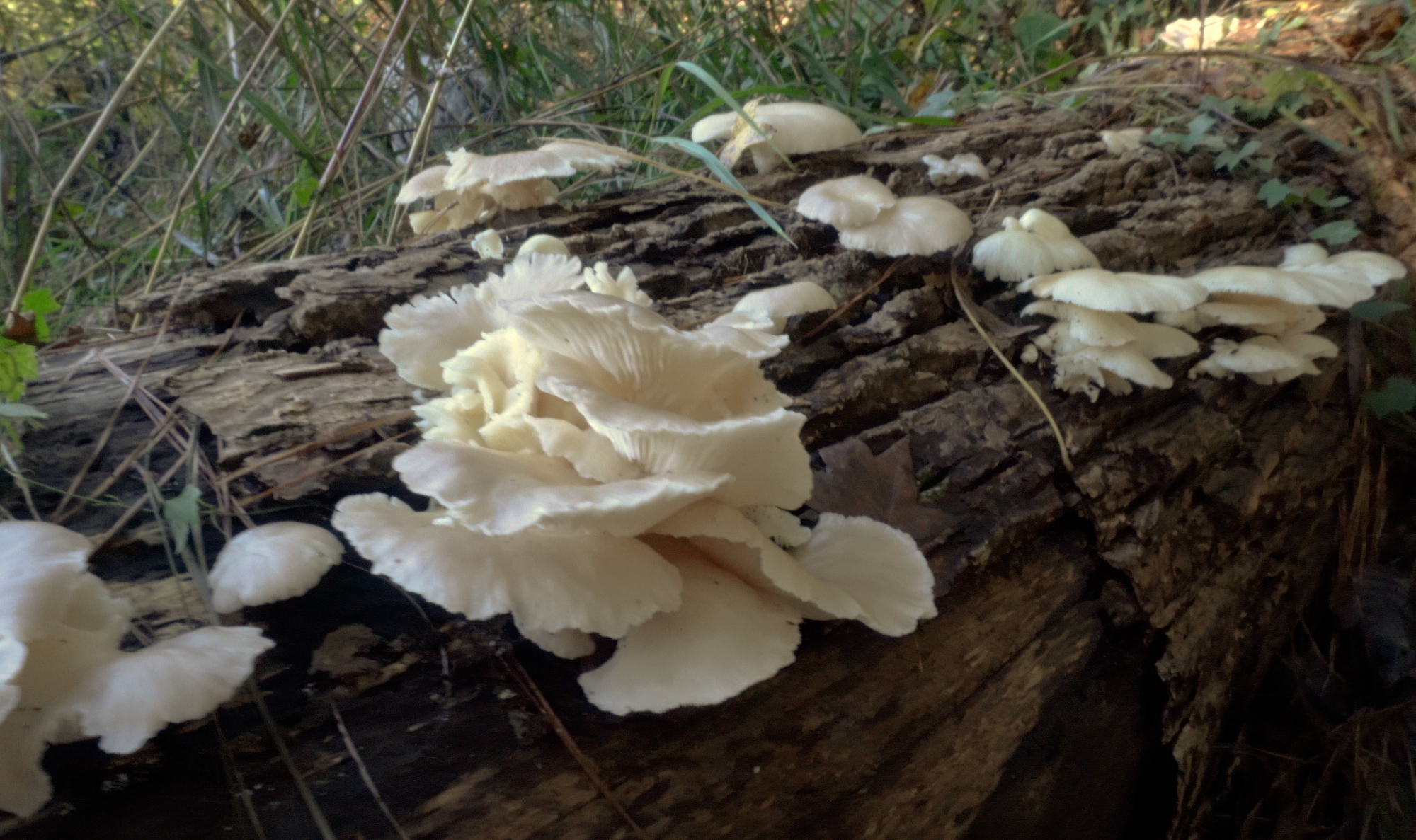
We begin by obtaining a sample from a mushroom, either as spores, mycelia, or a fragment of the mushroom itself. Spores can be acquired by collecting them from a mushroom, however this is an advanced technique that won’t be demonstrated in this article. Mycelia can be obtained by removing a small amount of the mushroom tissue and depositing it on a sterile growth medium for it to grow. To do this, we need a mushroom specimen to subculture from. This mushroom starting culture can be acquired in a number of ways. It can be purchased from a number of online vendors as mycelia growing on a nutrient medium in a test tube or Petri dish, a syringe filled with a liquid suspension of spores or mycelia, or fresh whole mushrooms can be purchased from a grocery store or farmer’s market. Although these methods often yield good results, I don’t find it as fulfilling as foraging a mushroom in the wild. Depending on where you live and the season, you may be limited in what you can forage. If your desired species is out of season, doesn’t grow locally, or is very difficult to find in the wild, purchasing a culture is a viable option. However, if the mushroom you desire can be found locally, it may be worth taking a trip or two into the woods to see what you can find.
Caution: There are many mushroom species that are toxic and can cause illness or death. Do not touch or eat a mushroom unless you are absolutely certain what it is. Even experienced mycologists and mushroom foragers have been known to become ill or die from misidentifying a mushroom. Therefore, it’s advised to forage with an experienced mushroom forager until you are confident in your identification abilities.
The mushrooms I sought for this project were cold-thriving varieties: oyster, lion’s mane, and shiitake. Shiitake are not often found in the wild, but we had some old logs that were inoculated several years ago and still fruit from time to time. Oyster and lion’s mane are native to my area and with some searching, I knew I could find at least one of these. I just needed to wait for the cooler weather to roll in and several days of high humidity. Following a few days of rain is often a good time to find newly-grown mushrooms.
Growth Media Preparation

The growth medium I’ll be isolating and growing the fungi on is malt extract agar (MEA). The malt extract provides nutrients for the fungus to grow and is slightly acidic, which aids in limiting some bacterial growth. Agar is an algae-based compound that solidifies the malt extract liquid solution into a solid gel, allowing for microorganisms to grow across the surface.
| Malt Extract Agar Recipe |
|---|
| 1 liter water |
| 20 g light dry malt extract (DME) |
| 20 g powdered agar |
| Pressure cook to bring to 120 °C at 15 PSI for 30 minutes |
After this mixture is heated and dissolved in the water, it cools and solidifies into a gel. While hot and still in a liquid state, it can be poured into a vessel and allowed to cool and solidify. To determine how much is needed, we need to consider the vessels we’ll be pouring it into. Petri dishes are small plates that have raised edges, which are designed to hold solidified agar in order to culture microorganisms. Since Petri dishes need to be sterile, glass is an inexpensive and reusable material option that is able to be sterilized in an autoclave or pressure cooker. Additionally, a metal cylinder can be useful for holding several Petri dishes while sterilizing and transporting them after sterilizing while keeping them from being exposed to the non-sterile outside environment.
For the 90 mm diameter Petri dishes I’ll be using, 20 ml per plate should be sufficient to completely cover the bottom of the dish. For 10 Petri dishes, that’s 200 ml to pour them all. Let’s raise that to 250 ml to account for pouring variability. Using the recipe above, we’ll need 250 ml water, 5 g DME, and 5 g agar. Weigh each of the powders out on a digital scale and combine them in a glass jar. If your jar has a screw-top lid, first make sure the lid is able to withstand the heat of a pressure cooker without melting. If it cannot, leave the lid off, otherwise tighten the lid and then unscrew the lid 1/4 to 1/2 revolution to allow the jar to depressurize while in the pressure cooker. If the jar is allowed to pressurize, it may explode (or implode), therefore ensure an air gap can always form while it’s being heated or cooled in the pressure cooker. It’s also a good idea to place aluminum foil over the jar’s top (especially if not using a lid) and extend down the neck of the jar a few inches to reduce the likelihood of contaminants depositing on or near where the agar will be poured from while the jar is being transferred out of the pressure cooker.
Once mixed and sealed with foil, place the jar, Petri dishes, and an appropriate amount of water in your pressure cooker, and follow its manufacturer’s instructions to heat and pressurize it. Typically, 120 °C at 15 PSI for 30 minutes is sufficient to sterilize 250 ml of fluid, however larger volumes may take longer to reach sterilization temperatures.
After sterilizing, allow the pressure cooker to slowly cool. Do not rush the cooling, as a drastic temperature or pressure drop can cause the heated liquid to begin boiling out of the vessel. However, since the liquefied agar will solidify at room temperature, don’t wait too long to pour the plates, since 250 ml of liquid will not stay hot for very long. Bring the pressure cooker as close to the laminar flow hood as you can and transfer the Petri dishes and jar of liquid agar into the hood. When working in the hood, make sure you’re always wearing gloves to reduce chances of contamination and sanitizing your gloved hands with 70 % isopropyl alcohol, ethanol, or a similar disinfection solution. Gently swirl the liquid agar in the jar to ensure it’s mixed well. Remove the Petri dishes from the metal cylinder and open a dish by picking up the lid, being careful not to touch the inside of the dish. Using quick, smooth, and careful motions, pour enough liquid agar into each Petri dish to cover the bottom, then place the lid on top. You may want to use something insulative like an oven mitt or beer coozy to pour the agar from the hot jar. Do not try to move dishes after you pour them except if you’re gently sliding them across a level surface. It is very difficult to keep a Petri dish level if you pick it up and you will likely either burn your hand and drop it or slosh the agar up the walls of the dish or spill it over the edge, which will only increase the likelihood of microorganisms contaminating your growth medium. Additionally, the lids of Petri dishes will often begin to condense water vapor on the inside of the lids, which can drip onto the agar surface or act as a route for contaminants to enter the dish if it’s placed upside down and the liquid drips down between the lid and base. A good way to reduce condensation and save space is to pour one Petri dish on top of another, creating a stacks of 5 or so Petri dishes. The hot bottom of the Petri dish in contact with the lid it’s resting on top of keeps the lid warm and reduces condensation. After pouring, allow the plates sufficient time to cool and solidify. Once the plates have reached room temperature, you can begin inoculating the agar media with your culture.
Culture Isolation
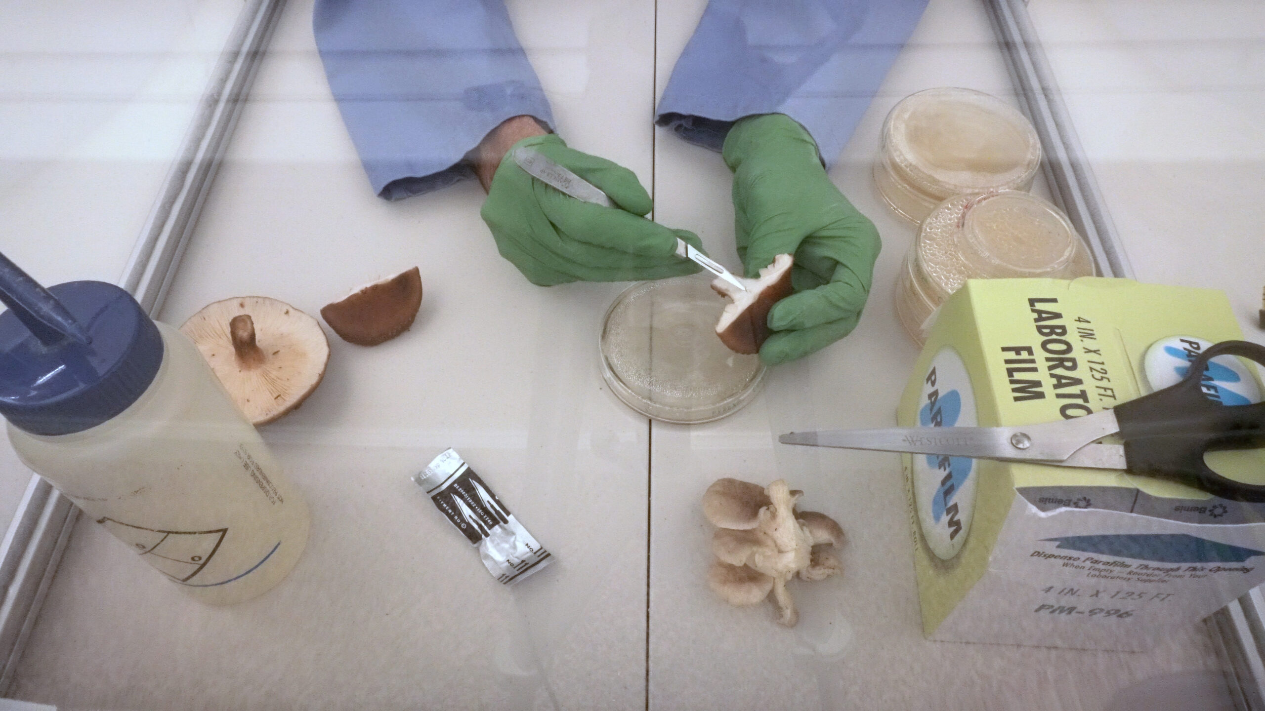
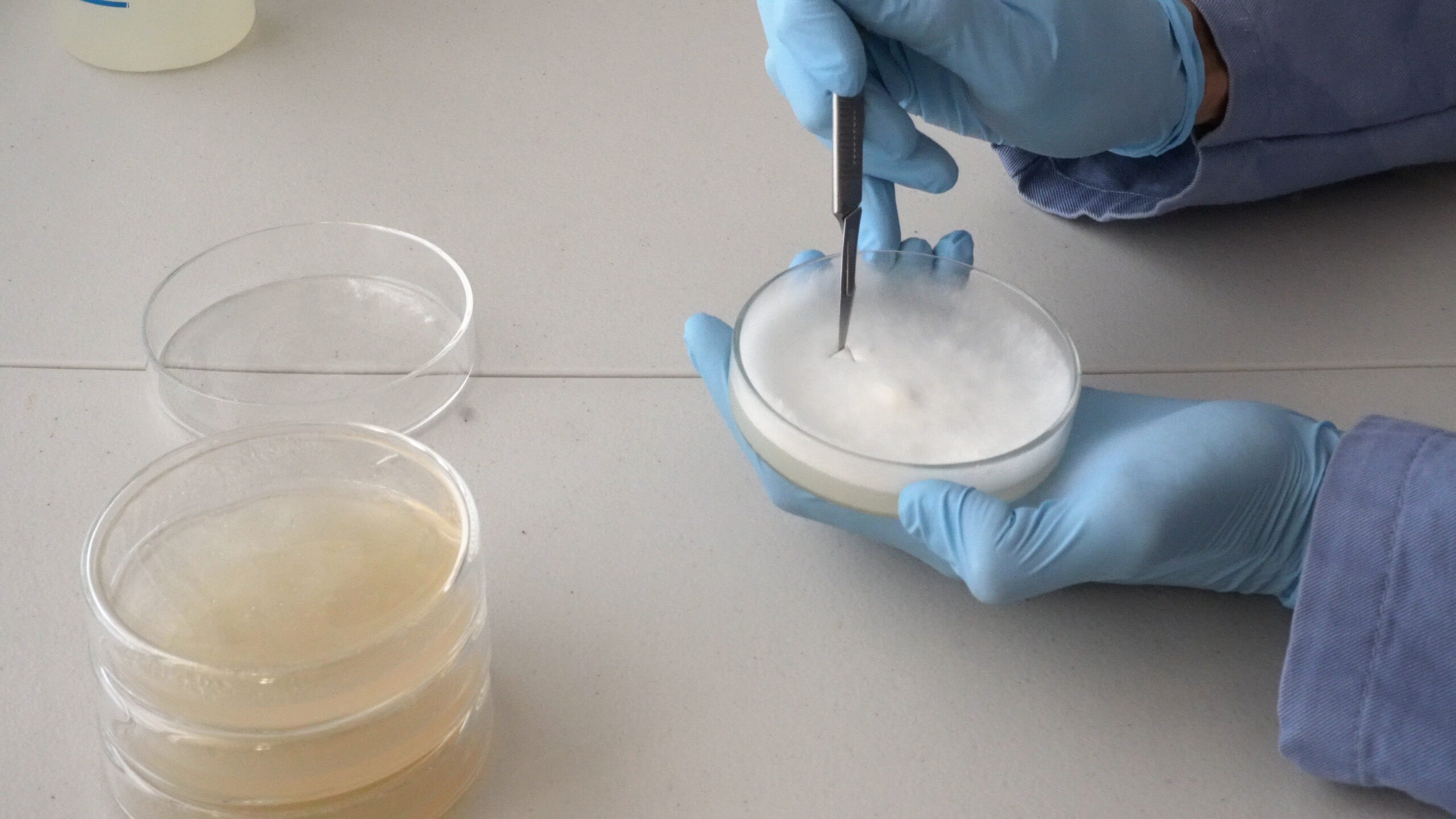
Isolating a mushroom culture involves growing the mycelia of a mushroom in a pure culture on a sterile growth medium. A pure culture is when only the microorganism of interest is grown. Growth of any other microorganism is considered a contamination. There are many other microorganisms in the air, on the surface of the mushroom, and sometimes within the mushroom. Therefore, if we are to grow this mushroom, and only this mushroom, we need to isolate and grow a pure culture from the mushroom we foraged earlier. To do this, we need to expose and excise a sample from the inner tissue of the mushroom where we’re least likely to find contaminating microorganisms.
In the flow hood, don latex or nitrile gloves and use alcohol to sanitize their exterior. Open a sterile scalpel blade, then rip open the mushroom stem or cap. Use the scalpel to cut a small piece of tissue near the center of the freshly-split mushroom. Try to excise a sample that looks clean and fresh. If you find bugs or discoloration, your sample may be too old or contaminated and you will need to either rip open another part of the mushroom or use another mushroom entirely. Once you excise a small sample of tissue, open a Petri dish and place the sample in the center on the agar surface. Place the lid back on the Petri dish and seal with a thin strip of paraffin film around the entire opening between the lid and base. This is done by gently stretching it as you pull it around the edge of the Petri dish while contacting both the lid and base to make a seal. For added protection, seal with two layers of film.
Produce several of these plates to increase the likelihood of isolation. You can also use a flame to sterilize the scalpel between sampling to further reduce the likelihood of contamination. If sampling different mushroom species, be sure to sterilize or use a new scalpel to prevent cross-contamination of the previous mushroom with the new one you are sampling. If culturing multiple species or strains, make sure to label the bottom of your plates to be able to distinguish them later. Place your plates in a dark place at room temperature to grow, checking them periodically.
Culture Propagation
After a few days of growth, you can begin to tell if your isolation was successful. Do not let the plates grow too long, as fast-growing contaminants can out-compete your mushroom culture and it may be difficult to determine if it is a contaminant growing or your mushroom culture. If you observe your plates every day, you should be able to easily distinguish contaminants from the mushroom culture. If you find any plates with contaminants, such as microbial colonies growing near or on the mushroom culture, or a slimy film growing from the inoculation point, set them aside. You are looking for only filamentous growth emanating from your point of inoculation that’s uniform in growth and color. This indicates there’s only a single microorganism growing, the mushroom you isolated from. Oyster, lion’s mane, and shiitake mycelia grow bright white, but this may not be the case for other species.
Set all plates that appear to have pure growth aside to another stack. Once you’ve gone through all plates, find the best plate from the pure culture stack. This will be the plate we use to propagate our isolate on to several more plates that we will use to grow more mycelial lawns.
With several fresh agar Petri plates prepared and gloves donned and sanitized in the flow hood, open your plate with growth. Inspect the margin (the youngest growth near the edge) of the growing mycelia and choose an area near the margin, but not too close to the edge of the Petri dish, as the edge of the Petri dish can sometimes harbor contaminants. Using a sterile scalpel, cut a small section of mycelia a few millimeters in size. You can cut completely through the mycelial lawn and through the agar. Carefully stab the piece you cut out and pull it from the plate and place it with the mycelia side down onto the center of the agar of a fresh Petri plate. This will allow the mycelia to immediately begin growing across the agar surface. Seal the plate with paraffin film. Repeat this process for several more plates. Our goal is to produce a sub-culture from the first plate of growth that we’ll further observe over the next few days to ensure the new growth remains pure and free from contamination. If you observe any contaminants, discard those plates (discard the agar and reuse the Petri dishes) and repeat the isolation process until you’re confident you are growing only one microorganism, your mushroom fungus. Incubate your plates in a dark place at room temperature for one to two weeks.
Spawn Production
Once you have your pure culture grown as confluent lawns on several plates, we can begin increasing the biomass of our culture on growth substrate known as spawn, which will be used later to inoculate our bulk substrate that will used to fruit mushrooms.
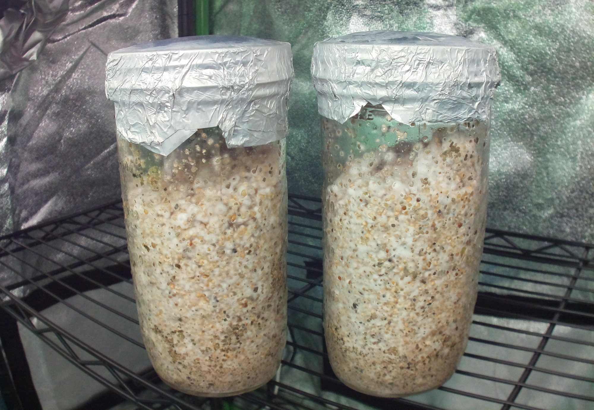
Bird seed is a nutritious and inexpensive growth medium that we’ll use as our spawn substrate. Using one or two ~12 oz. mason jars, add enough dry bird seed to fill 1/3 to 1/2 of each jar. Pour the bird seed from these jars into a pot of water to boil or into a nylon bag and steep in boiling water for 1 hour. Strain all water from the seed and return an even amount to each jar. You can add an ounce of wet perlite to each jar to make breaking up the bird seed during colonization a bit easier. Seal each jar and thoroughly mix the perlite with the bird seed.
If you have lid filters, replace the metal part of the lid with a filter and tighten the retaining ring on the jar. If you don’t have filters, crack each jar and place a piece of cloth or paper towel between the glass rim and lid to prevent a seal from being made while pressure cooking. Pressure cook the jars for 30 minutes at 15 PSI and let cool to room temperature before inoculating. In the flow hood, don and sanitize your gloves, then excise one or two pieces of mycelia from your most vigorously growing Petri plates and drop it into each jar. Seal the jars and place them in the environmental chamber to colonize.
If using lid filters on the jars, we’ll need to set our chamber humidity to somewhere between 80 % to 90 % to prevent humidity from being pulled out of the jars. After a few days you will notice the fungus being to colonize the bird seed from the mycelial fragment. Let this mycelia grow several inches undisturbed, then shake each jar to break up and distribute the broken mycelial fragments throughout the jar. This will speed up the time to colonize the entire jar by distributing the mycelia throughout. After another day or two, you should notice mycelia begin to grow from all parts of the jar. Do not let the mycelia grow too much, otherwise it will become difficult or impossible to break up the bird seed by shaking. Shake both jars for a second time to again break up the mycelia, then let it grow for another day or two. This time the mycelial growth should be vigorous and dense, indicating the spawn is ready to be used to inoculate the bulk substrate.
Bulk Substrate Production
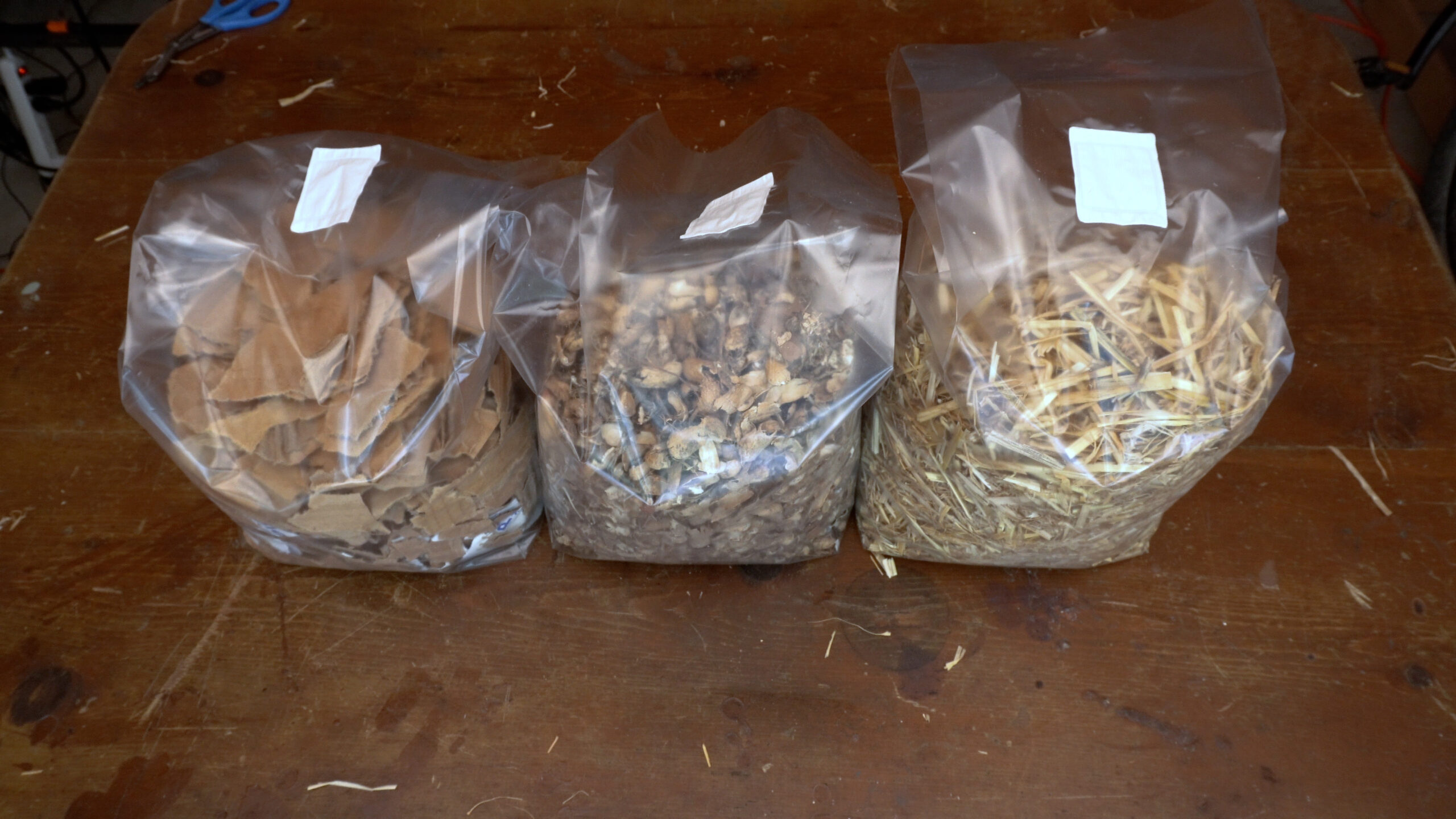
The bulk substrate is large amount of nutrient-rich material that we will use to fruit our mushrooms from. For oyster mushrooms, this can really be anything plant-based. I chose to use peanut shells, straw, and cardboard. Chop up the substrate into small pieces to both increase the surface area for the mycelia to contact as well as allow it to be more easily compacted into the growth bags. Fill each bag approximately 1/4 to 1/2 full. Next, we’ll need to hydrate the substrates by filling the bags with water and, depending on the substrate, using a weight to keep the material submerged under the surface of the water. Some substrates will absorb water quickly, while others may need to be submerged longer. We are aiming to hydrate the substrate until it can’t absorb any more water, then strain off the excess. When we strain off the excess, we want to remove any water the substrate cannot hold on its own. The substrate should be hydrated enough that releases only a few drops of water when squeezed firmly in your hand. When it’s been adequately hydrated, we can sterilize it.
Place a cloth strip in each bag opening so one end is near the substrate and the other hangs outside the opening of the bag. This is used to allow air to enter and exit the bag as the pressure changes in the pressure cooker. With the cloth strip in place, loosely roll the opening of each bag and place clips to hold the roll from coming undone. Do not overload your pressure cooker. You may need to do multiple batches to sterilize all your substrate. Pressure cook the bags for 30 minutes at 15 PSI, then allow them to return to room temperature before using.
Shake your spawn jars so the bird seed is broken up. In the flow hood, open the bags of substrate and remove the cloth strips. Evenly distribute the spawn into each bag of substrate, then tightly fold the opening a few times so as to keep some air in the bag but keep the bag sealed air-tight. Use a few clips to retain the fold and then shake the bag vigorously to evenly-distribute the spawn throughout the bag. Take off the clips, remove as much air as possible from the bags, tightly roll the opening to make an air-tight seal on each bag, then secure each roll with several clips. Make sure to stop the roll before the filter patch if one exists on your bag. Place the bags in the growth chamber. If your bags have a semi-permeable filter, you’ll need to set our chamber humidity to 80 % to 90 % to prevent humidity from being pulled out of the bags. Otherwise, you can wait to set the humidity until you open the bags for fruiting.
Bulk Substrate Colonization
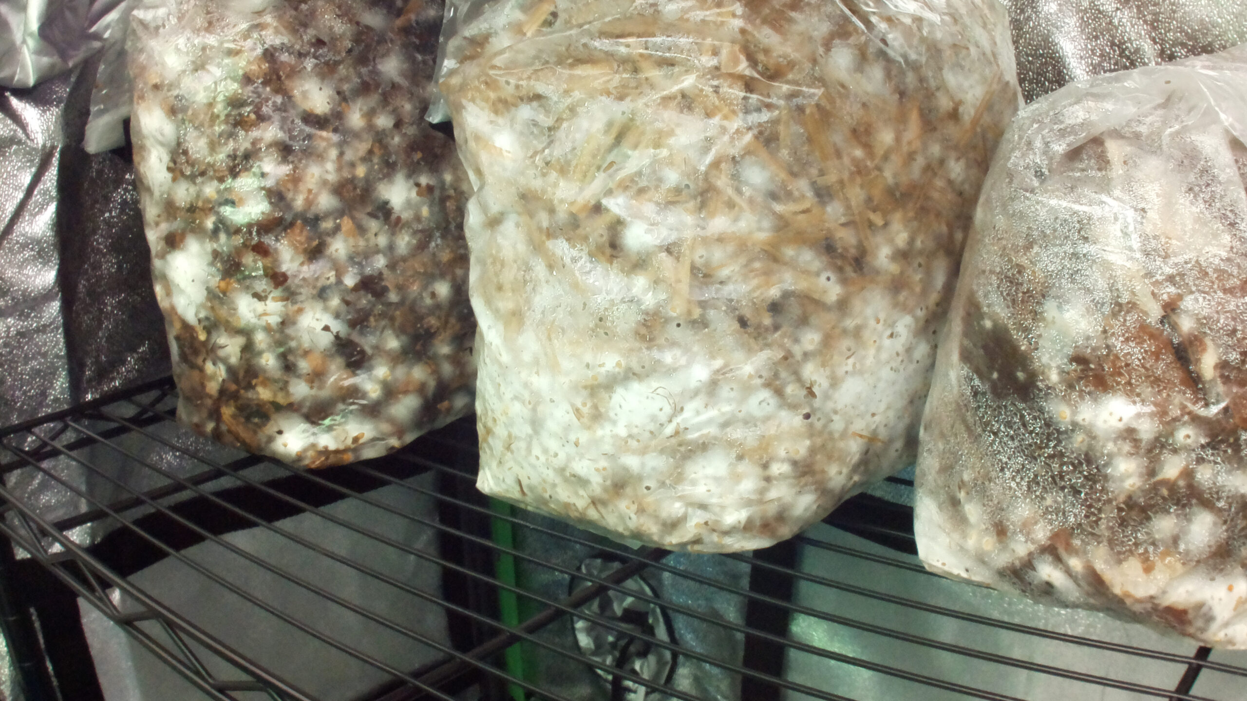
Over the course of the next few weeks, allow the substrates to become fully colonized, undisturbed. The fungus will convert the growth substrate into fungal biomass. During this process, the bags will fill with mycelia and become mostly white as the fungus invades every crevasse of the bag. Even after the exterior of the substrate has been colonized, the fungus will still be penetrating deep into the substrate. Therefore, even if we see the exterior of the substrate covered, it’s recommended to allow colonization to continue a bit longer in order to maximize the fungal biomass. One signal many fungi use to begin producing mushrooms is the depletion of resources, so allowing colonization to continue may improve the likelihood of successfully fruiting and yield.
Mushroom Primordia Formation
Once the bags have been fully colonized, we can begin preparing them for fruiting. There are two more growth stages we will be inducing: primordia, or pre-mushroom formation, then fruiting of the actual mushrooms.
Primordia will begin to form when the mycelia is exposed to a reduced carbon dioxide concentration and an elevated humidity somewhere near 95 % (note however that because I was prioritizing photo quality over yield, I never increased the humidity in my trials over 90 %). These conditions typically occur in nature when the fungus grows to the surface of the earth or substrate it’s been colonizing, indicating the environment has become favorable to form mushrooms to reproduce. While in the enclosed bag, carbon dioxide is generated and becomes concentrated to high levels, much like the fungus would experience when growing underground or within a tree, for instance. If we cut one or two 2-inch holes in the bag (or an X pattern), we allow the carbon dioxide to escape. The fungus will sense this reduction in carbon dioxide and begin forming primordia in this area. However, we need to ensure that the growth chamber environment removes this carbon dioxide so it doesn’t build up beyond 800 parts per million by volume (ppmv), otherwise primordia formation may be inhibited. Therefore, our carbon dioxide sensor will be used in the previously-set up feedback loop to turn on the exhaust fan and introduce fresh filtered air into the chamber and remove the carbon dioxide-laden air. This carbon dioxide monitor will need to operate continually since the fungus is respiring and continually converting oxygen into carbon dioxide, and will only increase respiration now that the bags have been ruptured.
For cold-thriving species, lowering the temperature can sometimes improve primordia formation. For other species, such as shiitake, cold temperatures and a physical impact (such as hitting a log with a hammer or slapping a bag with your hand) are required to initiate primordia formation. This might be one of the indicators for the organism in the wild to initiate pinning, such as after a dead tree it’s been colonizing falls to the ground.
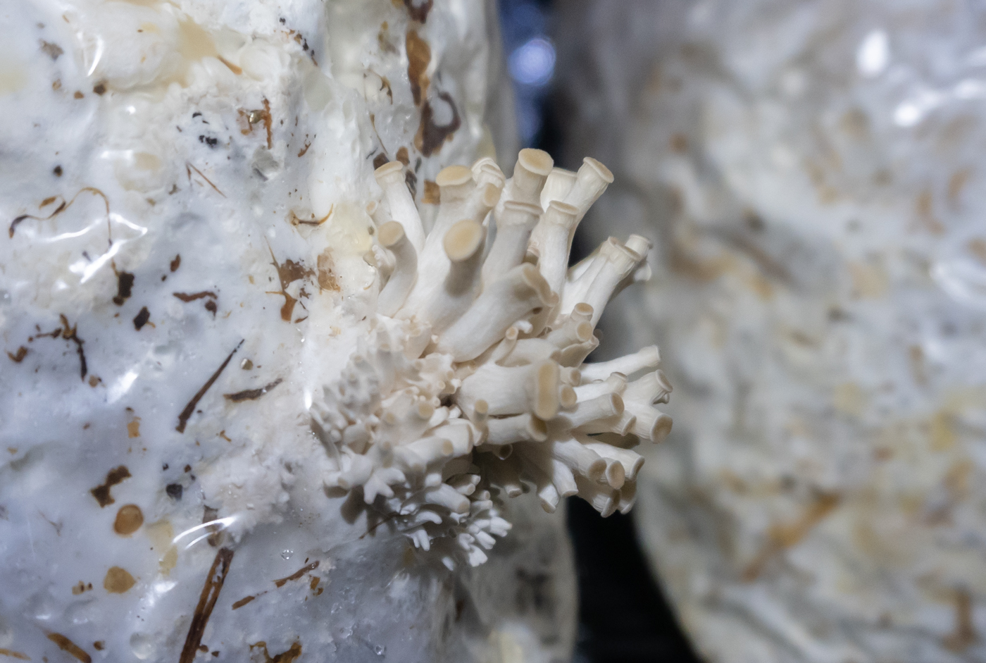
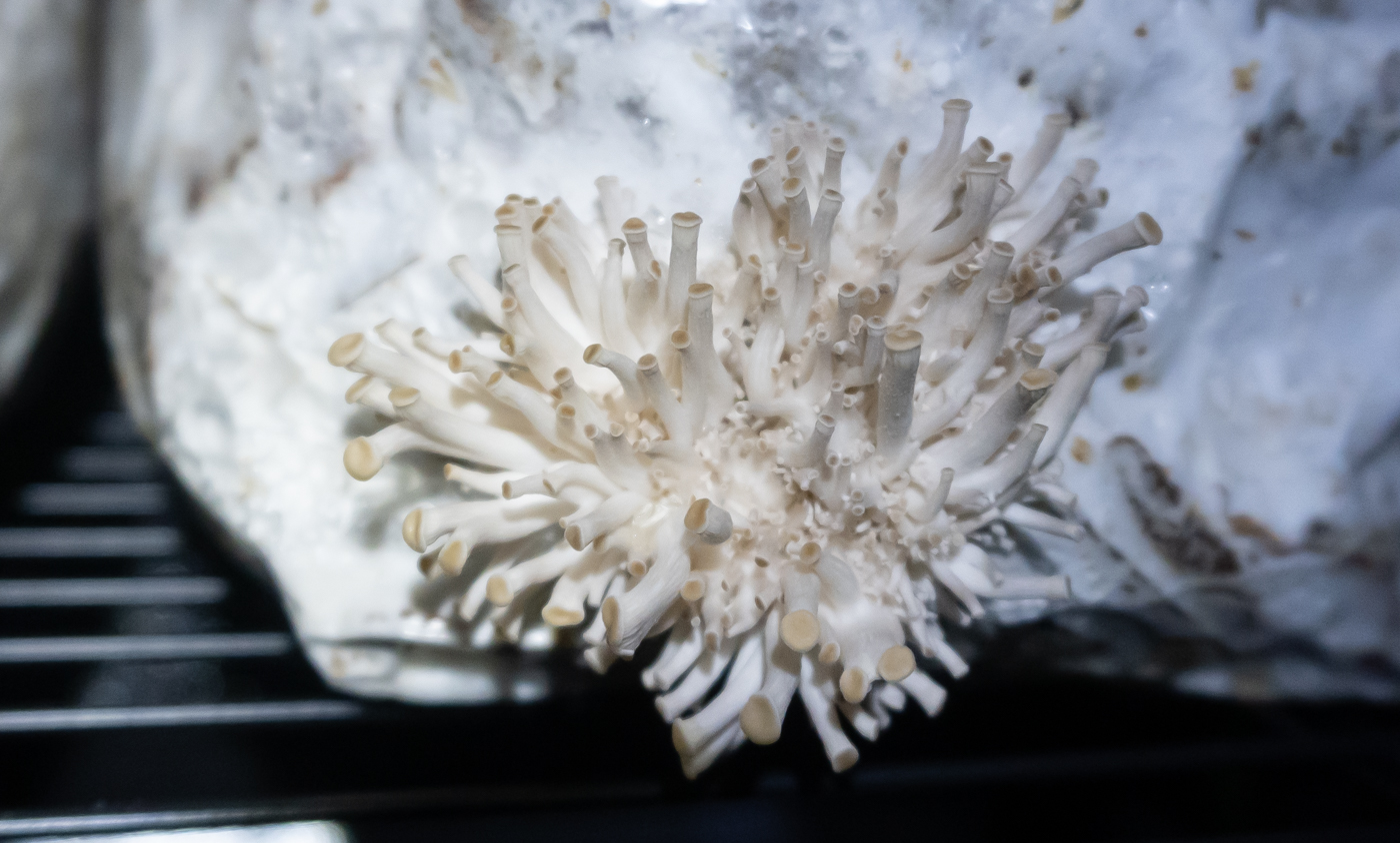
Several days after cutting the bags, you should notice tufts of mycelia start to grow near the openings of the bags. For oyster mushrooms, this is often a darker color than the surrounding mycelia and will start to take the form of small pins.
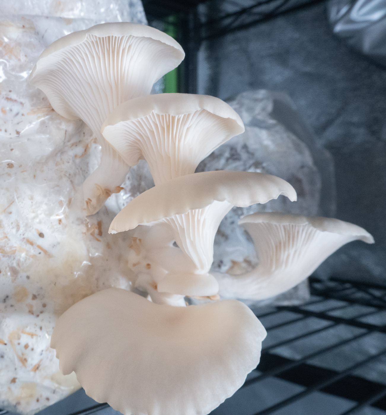
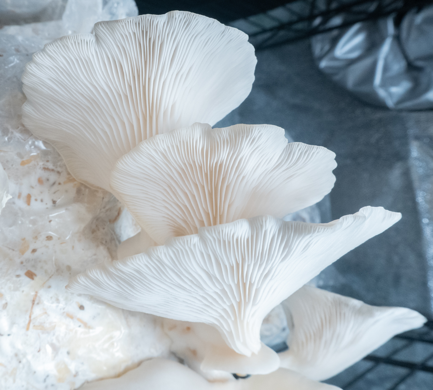
Mushroom Fruiting
These primordia will continue to grow in size over the next few days and then rapidly swell into mushrooms. Many primordia will abort and stop growing. This is normal and allows energy to be focused on producing fewer but larger mushrooms. At this stage, we will want to reduce humidity to 90 % to discourage mold growth and allow the mushrooms to continue to grow. Oyster mushrooms will be ready for harvest right before the edges of the mushrooms start to curl flat or upward and are still curled down. You can rip or cut them off the bag at the base of the stem or bunch and store them in a refrigerator for a few days, though they will be best enjoyed fresh. For long-term preservation, you can dehydrate and store them in an air-tight container.
After the first flush, or harvest, it’s possible to have several follow-up flushes every week or two, however yields typically diminish and the likelihood of contaminating molds appearing increases. If you notice mold growth, which typically presents as a dark colored growth (usually black, blue, or green), I suggest immediately removing the bag and discarding it, otherwise it’s likely to spread to other blocks. For this reason, many mushroom growers will only harvest once from oyster blocks.
Fried Oyster Mushroom Recipe
Why stop at harvest? Here’s a simple recipe for buffalo-style fried oyster mushrooms, taken from here with slight modifications.
Batter
- 10 oz. lager beer
- 3/4 cup all-purpose flour
- 2 tsp garlic powder
- 2 tsp onion powder
- 1 tsp cumin
- 1 tsp paprika
- 1/4 tsp sea salt
- 1/4 tsp ground black pepper
Breading
- 2 cups all-purpose flour
- 1 tbsp sea salt
- 1 tbsp chili powder
- 2 tsp garlic powder
- 2 tsp onion powder
- 1 tsp ground black pepper
- 1 tsp ground sage
- 1 tsp ground coriander
- 1 tsp smoked paprika
- 1/2 tsp ground nutmeg
- 1/2 tsp ground cumin
Instructions
- Combine the batter ingredients together in a large mixing bowl. Add 500 grams of fresh mushroom caps into this and coat well. Let them sit in this for about 20 minutes.
- Only after the oyster mushrooms have sat in the batter for 20 minutes, heat up several cups of vegetable oil to 355 °F to 360 °F in a deep pot. Use a deep frying thermometer to watch this closely. It shouldn’t go above 365 °F.
- Combine the breading ingredients together in another large mixing bowl.
- Once the oil is at the right temperature, take a mushroom out of the batter and coat well in the breading.
- Then go back into the other bowl of batter that hasn’t had anything in it and coat well. Go back in the breading and coat well. Then add to the frying oil.
- Fry mushrooms in batches. For each batch. it will take 2 to 3 minutes to get to a deep golden brown. Cook time will vary depending on the size of your mushrooms.
- Drain fried pieces over the pot with a slotted spoon and then place on a wire rack placed over a baking sheet. Do not use paper towels, as that could make the batter become soggy.
- To serve, top with pickles and drizzle hot sauce over the everything.

Future Directions
This has been a basic introduction to mushroom culturing and fruiting in an automated environmentally-controlled chamber. There are a number of improvements, optimizations, and changes that can be developed beyond these methods. These include:
- Regulation of temperature
- Removing the camera from the chamber to permit higher humidity
- Use different lighting to induce darker mushroom coloration
- and more…
References
Stamets, Paul. 2000. Growing Gourmet and Medicinal Mushrooms, 3rd Edition. Ten Speed Press.
Stamets, Paul. 1983. The Mushroom Cultivator: A Practical Guide to Growing Mushrooms at Home. Agarikon Press.
Toyota, Lauren. 2017. Buffalo oyster mushrooms. Hot for Food Blog.
Latest Articles
- Mushroom Cultivation Automation: From Foraging to FruitingMushrooms are a unique and often mysterious organism. They’re not quite plants and not quite animals. As a fungus, mushrooms represent a distinct evolutionary lineage. Fungi grow as a single-cell yeast form (used in beer, wine, and bread making) and multi-cellular, thread-like mycelia that often produce fruiting bodies (mushrooms) and sclerotia (e.g. truffles), and are responsible for the decomposition of the vast majority of dead plant matter. Understanding life cycle of mushroom fungi is a valuable skill if you wish to harness this knowledge for mushroom cultivation.
- Automated Hydroponic System BuildHydroponic farming is a method of growing crops without soil, with the main benefits of environmental and nutrient control, water conservation, and reduction of labor. This technique relies on a number of technologies that the principles of automation can be applied in order to improve yield and consistency. In this article and accompanying video, I’ll show you how to built a hydroponic system with basic components and automate it using the open source software Mycodo running on a Raspberry Pi single board computer.
- Remote Radiation MonitoringRadiation is the transmission of energy through space in the form of a particle or wave. These can be generated by instruments or… Read more: Remote Radiation Monitoring
- LoRaWAN Tracker and MapperLoRaWAN is a great long-distance, low-power transmission protocol. One of the questions that often comes up after deploying a gateway and nodes is… Read more: LoRaWAN Tracker and Mapper
- Outdoor LoRaWAN GatewayI’ve been heavily involved with sensors and remote sensing for many years. Recently, I’ve become intrigued with remote sensing, and began my exploration… Read more: Outdoor LoRaWAN Gateway
- Bringing a Vintage Telegraph into the Digital AgeI recently inherited a key on board (KOB) telegraph that my late grandfather used to practice Morse code with when he was a… Read more: Bringing a Vintage Telegraph into the Digital Age
Thank you for your time putting all this up for others to learn from and enjoy. I have Mycodo up and running (slowly but doing what’s needed) on a raspberry zero W. I have temporarily diy’d a small table into a small grow tent (17x23x27). I lined it with reflectix with a 3mil contractor bag tub. I have a rapti-fogger for humidity, a small 80mm AC Infinity fan for circulation once per hour for 30 secs on Med speed. The grow light and other stuff is controlled through a Kasa 6-outlet wi-fi power strip (I had to modify your 3 plug output python file to adapt to the 6 plugs, but working great. The raspberry pi has an AHT10 (temp, humidity) sensor connected through I2C. The system looks stable, so now to start a fruiting cycle on an oyster mushroom block.
Again, thank you for taking the time to educate others.
Robert H.
grow light improves anything ?
For some mushroom varieties, light can help fruiting.
Incredible project. I appreciate the impressive detailed write up. Thank you for sharing your knowledge and this complete work of art!
Exactly what I was searching for. Thank you so much for sharing this with us.
Kyle G, really appreciate your knowledge and work! I’m attempting to produce your setup, just ordered all the specified parts, keep you posted as to how it goes. If it works you will have saved me a lot of endless hours in the day to day work schedule, which is huge!! If I wanted to donate to you, what’s the best way? Thank you for providing your work open source and not keeping this knowledge for yourself!!
Glad to hear! I have a donate page at https://kylegabriel.com/donate
This is amazing, and the write up is so awesome. Have you thought about adding machine learning to inspect the images from the camera and alert when the mushrooms are ready for cultivation? A set and forget system would be incredible for continued home use.
This is sweet work! I am tracking down the hardware now to set it up! I love what you’ve done! I’ll definitely donate after I have this running! SO STOKED!