
Last Updated: August 28, 2022
Hydroponic farming is a method of growing crops without soil, with the main benefits of environmental and nutrient control, water conservation, and reduction of labor. This technique relies on a number of technologies that the principles of automation can be applied in order to improve yield and consistency. In this article and accompanying video, I’ll show you how to built a hydroponic system with basic components and automate it using the open source software Mycodo running on a Raspberry Pi single board computer.
Many of the aspects that make hydroponic farming so efficient can also make it challenging to implement. Water and nutrients must be provided in a balanced ratio while being constantly monitored and adjusted as plants develop. Temperature regulation can also become a problem since the circulating water system acts as a heat pump. Additionally, the microbial communities that can benefit or harm your crops are now competing in an aqueous rather than a terrestrial environment, sending us even further into unknown and potentially dangerous territory. And to make matters worse, if you have a prolonged power outage, you may need to manually water or have a generator to keep the water pump going, else you may injure your crops.
Even with these challenges, there are several aspects that make hydroponics attractive (Barbosa et al. 2015). An optimal amount of nutrients can be supplied directly to plant roots in an immediately-usable form. Plants can be grown in areas with poor soil or limited space, or grown vertically to maximize plant density. Water waste is reduced by recirculating it back into the system. There’s also no need to worry about weeds.
Although there are a number of different hydroponic and cultivation techniques, this article explores only one of the ways to build a hydroponic system and apply principles of automation to monitor and regulate it. This is meant primarily to demonstrate the process of applying automation techniques, which can be adapted to many other systems. And while the hydroponic system I built is relatively small, it’s a modular design that can be scaled to different growing spaces, be it a small grow tent or a large commercial greenhouse.
Support
If you find this article or video useful or you use Mycodo and want to support my future work and software development, consider becoming a Patron at patreon.com/kylegabriel
Introduction
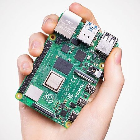
At the core of this automated hydroponic system is the Raspberry Pi single board computer. This $35 computer is only the size of a deck of playing cards, but it has all the components you would find in a full computer, including CPU, RAM, video/audio output, USB, WiFi, Bluetooth, Ethernet, and micro SD slot. The most important feature of the Raspberry Pi for our application is its general purpose input-output (GPIO) pins, which will be used to connect inputs, such as switches and sensors to measure the environment, and outputs such as pumps and relays to move liquids and control electrical devices that will manipulate the environment.
Until recently (this month, in fact), the major Achilles Heel of the Raspberry Pi has been an inability to boot from external storage devices, forcing the use of a micro SD card. Micro SD cards were designed for cameras where there are minimal read/write operations. Running a full Linux operating system along with a time-series database recording measurements severely reduces the life expectancy of the SD card and reduces the stability of the system due to file system corruption. In May 2020, firmware that allows the Raspberry Pi 4 to natively boot from an external storage device entered beta. This drastically improves its stability and suitability in critical automation applications.
The software which will be installed on the Raspberry Pi to automate the hydroponic system is a free and open source software package I’ve developed, Mycodo, which is essentially a universal tool for environmental measuring, monitoring, and manipulation, and has been used for a number of interesting and diverse applications. Mycodo is a user-friendly yet powerful tool for building automation into almost any system. Below is a brief overview of the functionality that will be configured in Mycodo to operate as a hydroponic system controller:
Hydroponic System Automation Features
- Measure water conditions: pH, electrical conductivity, temperature, level, and flow.
- Measure air conditions: temperature, humidity, vapor pressure deficit, and carbon dioxide (CO2).
- Control relays to modulate lights, air exhaust fan, and humidifier.
- Control four peristaltic pumps to dispense specific volumes of solutions: acid, base, nutrient A, and nutrient B.
- Automatically adjust water to target pH range by dispensing acid/base solutions.
- Automatically adjust water to target electrical conductivity range by dispensing nutrient solutions.
- Automatically adjust air to target humidity, temperature, and CO2 concentration ranges by modulating an exhaust fan and humidifier.
- Automatically regulate air vapor pressure deficit (VPD) with a humidifier and exhaust fan, using a PID controller.
- Use timers to schedule grow lights, air exhaust, and a DSLR camera shutter for high quality time-lapse photography.
- E-mail alert notifications if select measurements fall outside acceptable ranges (e.g. temperature too high, water level too low, water flow has stopped, etc.).
- Measure electrical energy usage with a transformer to automatically calculate operating costs.
- Use the Raspberry Pi Camera to monitor plants with a live video stream and conduct time-lapse photography of plant growth.
- Configure dashboards with gauges, graphs, camera feed, and other widgets to view all relevant data on a single page.
- Forward port 443 through your router to the Raspberry Pi to be able to access the Mycodo web interface from anywhere with internet access (using a user login system for security).
Disclosures
I reached out to Atlas Scientific to ask if they would be willing to contribute to this project, and they were kind enough to donate 4 peristaltic pumps, an electrical conductivity sensor kit, and a pH sensor kit. I’ve used Atlas Scientific instruments for years and have incorporated support for several of their sensors and pumps into Mycodo, all prior to this project. I’d like to thank them for their donations and for making quality products.
Additionally, I earn a commission from qualifying purchases. What this means is if you click a link on my site to a product and purchase it, I may earn a small commission, without any additional cost to you. Please consider using these links if you would like to support my work and see more like it in the future.
Materials & Parts List
Each part of building and operating the hydroponic system will be covered in detail. As needs vary, so too will the choice of materials one incorporates into his or her system. The materials list below is only meant to provide a complete list of the components used in this particular build.
Tools (Essential)
These tools are the minimum required to build this system, unless you want to adopt some creative fabrication techniques.
| Description | Purchase |
|---|---|
| Soldering Iron | Amazon |
| Solder | Amazon |
| Saw or Dremel with Cutting Kit | Amazon, Amazon |
| Heat Gun | Amazon |
| Cordless Drill | Amazon |
| Drill Bit Set (16-Piece) | Amazon |
| Step Drill Bit (1/4 to 1 3/8 in.) | Amazon |
| 1 3/4 in. Hole Saw Bit | Amazon |
| Screwdriver Set | Hardware Store |
| Thread Seal Tape | Hardware Store |
Tools (Non-Essential)
These tools aren’t required to build the system but are useful for verifying measurements and tuning the system.
| Description | Purchase |
|---|---|
| Photosynthetically active radiation (PAR) Meter | Amazon |
| Clamp Electrical Current Meter | Amazon |
Base Hydroponic System
These are the components necessary to build the base hydroponic system that can operate to grow crops but will need to be manually operated. The materials further below will automate various parts of the system.
| Description | Purchase | Quantity |
|---|---|---|
| Grow Tent | Amazon | 1 |
| Grow Light | Amazon | 1 |
| Microtube Grommet | AmHydro | 6 |
| Microtube | AmHydro | 6 |
| 2 in. x 3 in. Vinyl Downspout | Home Depot | 1 |
| 4 in. PVC Sewer and Drain Pipe | Home Depot | 1 |
| 4 in. PVC Sewer and Drain Cap | Home Depot | 2 |
| 3/4 in. Bulkhead Union | Home Depot | 1 |
| 1 1/2 in. ID Swimming Pool Hose (2 feet) | Home Depot | 1 |
| 1 in. PVC Pipe | Home Depot | 1 |
| 1 in. PVC End Cap | Home Depot | 2 |
| 1 in. x 1 in. x 1/2 in. PVC Tee (S x S x FPT) | Home Depot | 1 |
| 1/2 in. ID x 1/2 in. MIP Plastic Hose Barb Adapter Fitting | Home Depot | 1 |
| 10 Gallon Bin | Home Depot | 1 |
| Submersible Water Pump | Amazon | 1 |
| 1/2 in. ID Clear Vinyl Tubing | Home Depot | 1 |
| Stainless-Steel Hose Clamp (3/8 in. – 7/8 in.) | Home Depot | 1 |
| Stainless-Steel Hose Clamp (3/4 in. – 1 3/4 in.) | Home Depot | 1 |
| Nylon Filter Bags | Amazon | 1 Pack |
| Plant Growth Nutrient Solutions (Two Part, A and B) | Amazon | 1 |
| pH Adjustment Solutions (Up/Base and Down/Acid) | Amazon | 1 |
| Mycostop Biocontrol (Streptomyces griseoviridis bacteria) | Amazon | 2 Grams |
Planting
These are the materials for germinating and growing plants.
| Description | Purchase | Quantity |
|---|---|---|
| Seeds | Johnny’s | Choose |
| Rockwool Grow Cubes or Horticubes | Amazon, Amazon | 1 Pack |
| Seed Germination Tray and Dome | Amazon | 1 |
| Waterproof Seedling Heat Mat | Amazon | 1 |
Environmental Monitoring and Regulation System
| Description | Purchase | Quantity |
|---|---|---|
| Raspberry Pi v4 | Amazon | 1 |
| Micro SD Card (32 GB) | Amazon | 1 |
| Raspberry Pi v2 Camera Module | Amazon | 1 |
| Raspberry Pi Camera Ribbon Cable | Amazon | 1 |
| HDPE Plastic Mounting Panel | Amazon | 1 |
| 6-Outlet Power Strip | 1 | |
| 20 character, 4 line I2C LCD | Amazon, DFRobot | 1 |
| #1 x 7/16 in. Stainless Steel Screws | Amazon | 1 Pack |
| Round Nylon Spacers (H 6 mm, OD 7 mm, ID 4 mm) | Amazon, | 1 Pack |
| Mini Breadboards | Amazon, | 1 Pack |
| Jumper Wire Kit | Amazon, | 1 Pack |
Power Control Box
These materials are for building a power control box that has 4 individually-controllable outlets, allowing any 120 VAC device to be controlled by the automation system.
| Description | Purchase | Quantity |
|---|---|---|
| 6 in. x 6 in. Junction Box | Home Depot | 1 |
| RJ45 Panel Mount Connector | Amazon | 1 |
| RJ45 Surface Mount Jack | Amazon | 1 |
| RJ45 Crimper, Connectors, and Cable Test Tools | Amazon | 1 |
| RJ45 CAT-6 Ethernet Cable (5-foot) | 1 | |
| IEC 320 Panel Mount Power Socket | Amazon | 1 Pack |
| IEC 320 Power Cord | Amazon | 1 |
| Wall Outlets | Home Depot | 2 |
| 2-Gang Wall Plate | Home Depot | 1 |
| 2-Channel Relay Module (Mechanical, 10-Amp) | Amazon | 1 |
| 2-Channel Relay Module (Solid State, 2-Amp) | Amazon | 1 |
| 14 Gauge Copper Wire | Home Depot | 1 Spool |
Water Condition Sensing
These materials enable various water chemistry to be measured and provides feedback for the water dosing system.
| Description | Purchase | Quantity |
|---|---|---|
| Atlas Scientific PT-1000 Temperature Sensor Kit | Amazon | 1 |
| Atlas Scientific EZO Carrier Board (for Temperature Sensor) | Amazon | 1 |
| Atlas Scientific pH Sensor Kit | Amazon | 1 |
| Atlas Scientific Electrical Conductivity Sensor Kit | Amazon | 1 |
| Aquarium Specimen Container | Amazon | 1 |
Water Dosing
These materials enable the water chemistry to be adjusted by dispensing different liquid solutions.
| Description | Purchase | Quantity |
|---|---|---|
| Atlas Scientific Peristaltic Pump | Amazon | 4 |
| Silicone Tubing (ID 3 mm x OD 5 mm) | Amazon | 1 |
| 1/8 in. Hose Barb Union | Amazon | 1 Pack |
| 12-Volt 5-Amp DC Power Supply and Female Barrel Connector | Amazon | 1 |
Water Flow and Level Sensing
These materials enable the measuring of water conditions that allow for the system to be monitored for proper operation.
| Description | Purchase | Quantity |
|---|---|---|
| Atlas Scientific Flow Meter | Atlas Scientific | 1 |
| Atlas Scientific Flow Meter Totalizer | Amazon | 1 |
| Atlas Scientific EZO Carrier Board | Amazon | 1 |
| 1/4 in. O.D. x 3/8 in. MIP NPTF Push-to-Connect Adapter Fitting | Home Depot | 2 |
| 3/8 in. FIP Brass Pipe Coupling Fitting | Home Depot | 2 |
| Water Level Float Switch with Pipe Mount | Amazon | 1 |
| Assorted Resistor Kit | Amazon | 1 |
Air Condition Sensing
These materials enable various air conditions to be measured.
| Description | Purchase | Quantity |
|---|---|---|
| HTU21DF Temperature/Humidity Sensor (or AM2315, SHT31, etc. See Supported Sensors) | Amazon, Amazon, Amazon, DFRobot, DFRobot | 1 |
| Dupont Crimping Tool and Connectors | Amazon | 1 |
| MH-Z19B CO2 Sensor | Amazon, Tindie | 1 |
| UART to USB Converter (USB Interface) | Amazon | 1 |
Electrical Power Sensing
These materials enable the amount of power consumed by the system to be measured.
| Description | Purchase | Quantity |
|---|---|---|
| Analog-to-Digital Converter | Amazon, DFRobot | 1 |
| AC Current Sensor with Split Transformer or Greystone CS-650-R1 Solid Core Current Sensor (only one, not both) | Amazon | 1 |
| Extension Cord (1 ft.) | Amazon | 1 |
3D Printed Parts
These are various 3D models of simple parts I created and printed with my 3D printer that helped with the build.
| Model 1: Sensor Probe Reservoir Lid |
| Model 2: Bottle Support Mount |
| 3D Printer: Creality Ender 5 Pro |
| 3D Modeling Software: Autodesk Fusion 360 |
| 3D Slicing Software: Ultimaker Cura |
| 3D Printer Control Software: OctoPi (OctoPrint for the Raspberry Pi) |
Building the Hydroponic System
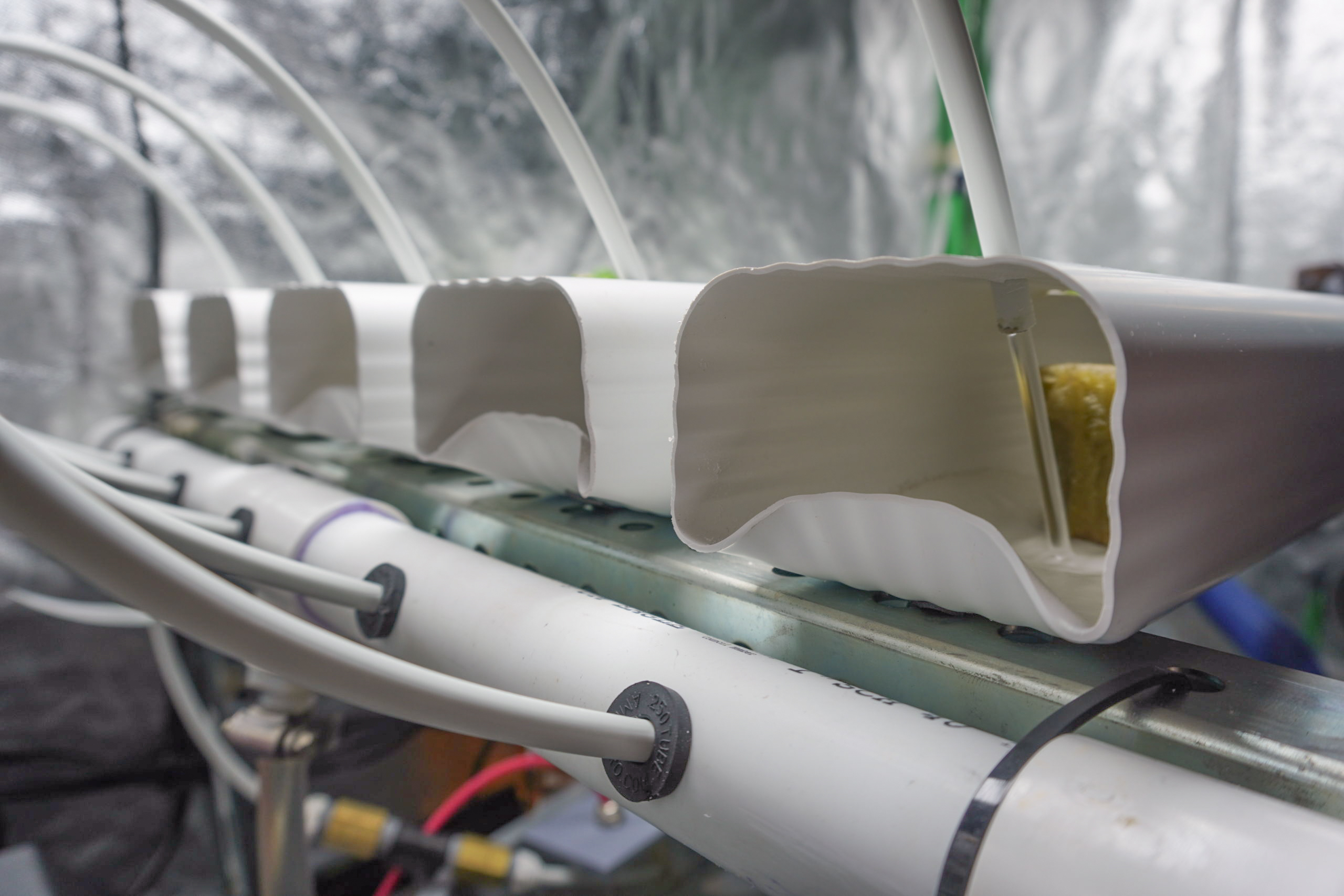
This hydroponic system being built relies on a method known as the nutrient film technique (NFT). These systems are popular for their ease of use and the high yields that can be achieved. Plants that benefit the most from NFT are leafy greens, such as lettuces and herbs.
The design of an NFT hydroponic system is simple. Water is pumped up from a reservoir to fluid channels, where the channels are placed at a slight angle to allow the water to flow from the high end to the low end by gravity, where the water is then returned to the reservoir. Plants are placed in holes cut in the top of the channels and are supported by a growth substrate. The substrate provides a place to absorb water and/or support the plant. As the plants grow, their roots extend into the fluid flowing across the bottom of the channels. This particular design was inspired by do-it-yourself projects as well as systems built by the commercial hydroponics company AmHydro, from which the grommets and microtubes being used in this build were purchased.
Frame
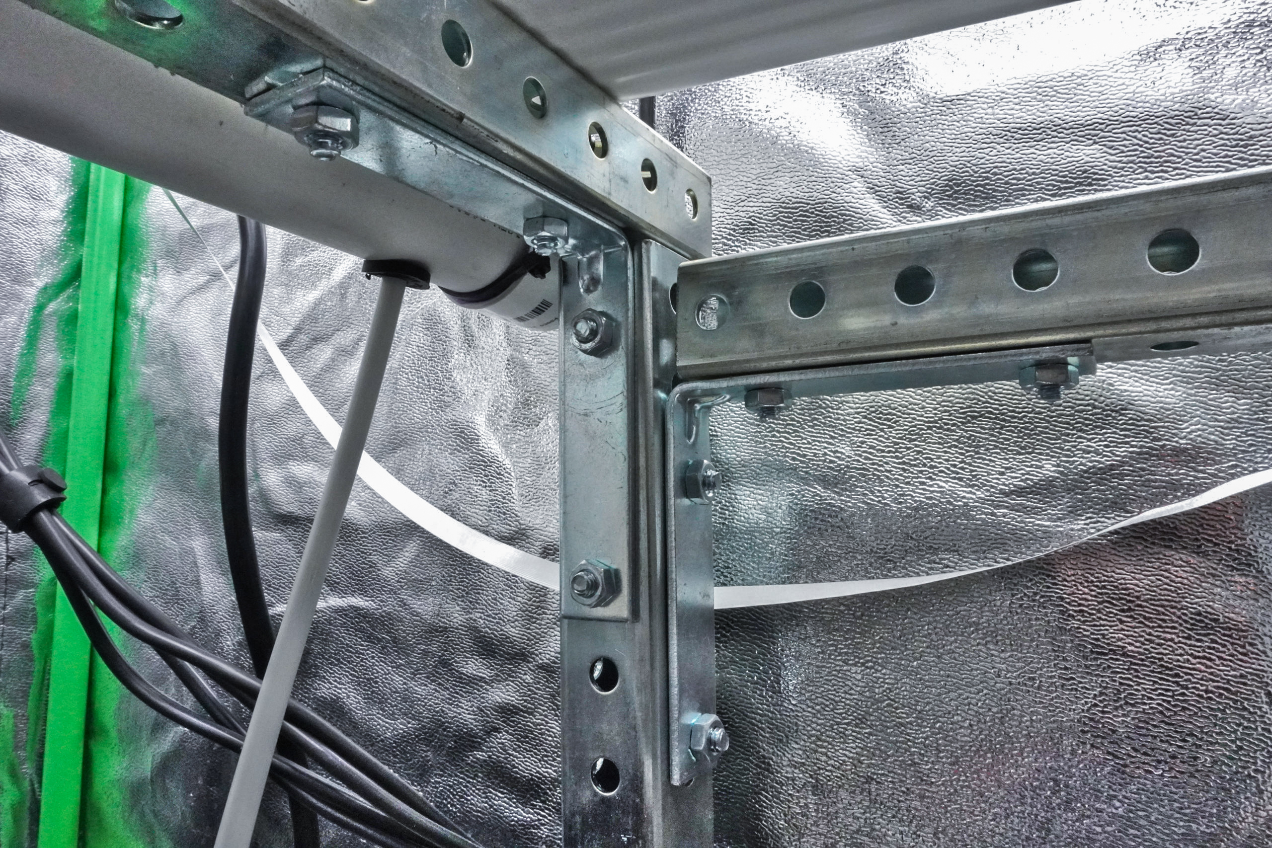
A frame is needed to support the water channels as well as the water inlet and collection pipes. One end should be higher than the other to allow water to flow through the channels by gravity. I had 1-inch punched square steel tubing left over from a previous project, so this is what I used to construct my frame (drawing below). However, there are many ways to support channels, from raising one end of a table to building a custom frame. Steel is a relatively expensive material, so I would suggest using angled aluminum bar or tubing if you’re going to design your own frame. Another inexpensive and modular option is to use 3/4 inch electric metallic tube, a metal tube cutter, and Maker Pipe connectors.
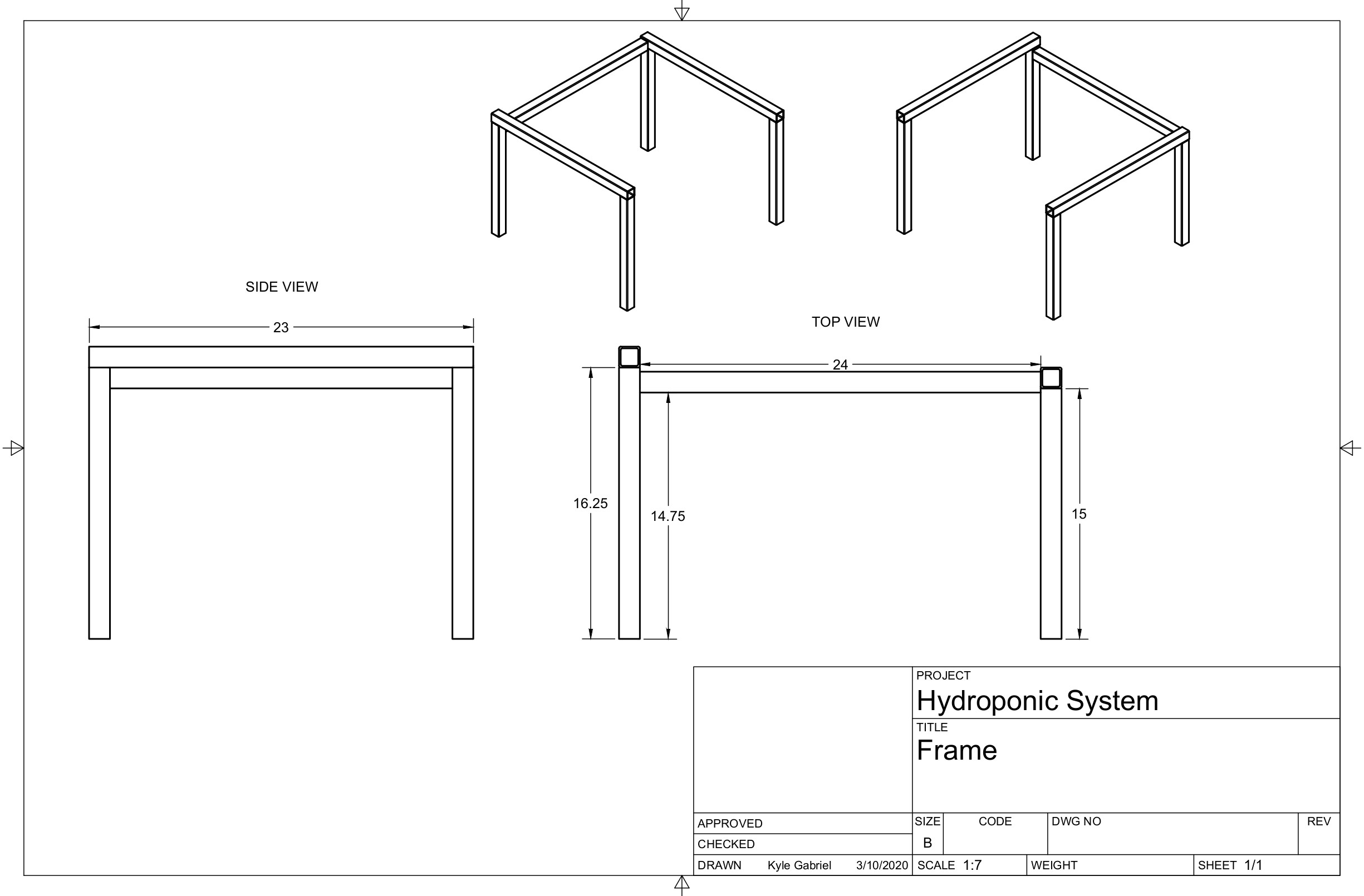
Between 2° and 3° is a sufficient angle for water to flow through the channels. If the angle is too small, water may not flow fast enough through the channels and cause overflow and spillage on the inlet edge. Cut the square tubing into two 16.25-inch lengths and two 15-inch lengths, to serve as two long and two short leg sets. Cut two 23-inch lengths to attach to the top of each leg set (upon which the channels will rest), and bolt flat steel bars angled at 90° to secure them to the legs. Secure all 90° flat bars using 4 bolts to improve rigidity, so no cross-bracing is necessary. Cut a 24-inch length and bolt each end to each of the rear leg sets, to serve as a spine. This spine will also later serve as a support for the pumps to mount to.
Water Channels
The water channels are made by cutting vinyl gutter downspouts into five 2.5-foot segments. I used 2 in. x 3 in. downspouts, but 3 in. x 4 in. downspouts were also available, which could be a good option if you have more space or are building a system with longer channels or for larger plants. Using a hole saw, cut 1.75-inch diameter holes on the widest side of the channels, at a spacing of approximately 6 inches, on center. I alternated the cutting so when the channels were placed side-by-side, the holes alternated and formed a checkerboard pattern, which maximizes space between plants to grow. Drill a 1/4-inch hole in the top of each channel, on the inlet side, about 3 inches from the end, which will be used to supply water to each channel. The bottom edge of the inlet side of each channel can also be heated and bent upward to reduce the chance of water spilling out in the event water backs up in the channel (e.g. due to excessive root growth or if the channel angle isn’t steep enough). Place the channels on the frame, with the inlet sides with the 1/4 inch holes resting on the higher end.
Different plants may require different channel spacing. Additionally, channels can be made with holes closely-spaced (2 inches on center) to be used as nursery channels to grow many seedlings prior to transplanting to finishing channels with wider spacing for mature plants.
Water Input
To supply water to each channel, 1-inch PVC is routed along the length of the inlet side of the frame and connected to a water pump. Cut two 11-inch PVC lengths, then cement a PVC tee in the center and PVC end caps to the ends. Screw a 1/2-inch hose barb adapter into the tee after applying thread seal tape. Drill five 3/8-inch holes into the inlet pipe, one in front of each channel. Remove any burs and install a microtube grommet into each hole. Secure the inlet pipe to the frame edge with zip-ties or other fasteners, just under the channels. Connect one end of a 1/2-inch inner-diameter hose to the inlet pipe’s hose barb with a hose clamp and the other end to the water pump. Last, connect a microtube from each grommet to each channel’s 1/4-inch inlet hole.
Water Collection
To collect the water exiting the channels, we’ll construct an open pipe on the outlet side to route the water back to the reservoir. Cut a 22-inch length of 4-inch PVC pipe (S&D PVC that I am using for this project is thinner, cheaper, and easier to work with than schedule 40 PVC, but it is not rated as food-safe. For safety, always use food-grade, schedule-40 PVC). To increase the area to open the 4-inch pipe, cut two PVC end caps to remove excess plastic so the caps are shortened to a width of about 3/4 inch, then cement them to the ends of the pipe. Mark a straight line down the length of the pipe, from end cap to end cap, then cut the pipe along the mark. Cut about 4 inches at a 90° angle at both ends, creating a flap that can open down the length of the pipe. Using a heat gun, slowly and evenly heat the pipe along the flap hinge while applying slight pressure to bend the flap open. Once the flap opens far enough to be able to fit the channels in, stop heating the pipe and allow it to cool and harden in the open position.
Fit the channels into the pipe opening along the length of the pipe and position the pipe at the lower end of the frame to determine an optimum mounting position. In the center of the pipe, mark the lowest point where water will pool. This is where a 1.25-inch hole should be drilled to attach the bulkhead union that will drain the water back into the reservoir. Once the hole has been drilled, use a heat gun to gently heat around this hole so when the bulkhead is tightened, the curved PVC flattens so the rubber gasket of the bulkhead forms a water-tight seal. Secure the 4-inch pipe to the edge of the stand with large zip-ties or other fasteners and insert all the channels. Attach swimming pool hose to the bulkhead with a hose clamp and secure the other end in the water reservoir. Attach a nylon filter bag to the end of the hose to catch any large particles from entering the reservoir that may potentially clog the pump (e.g. rockwool, plant material, etc.).
Fill the water reservoir with a few gallons of water until the pump is fully submerged. Turn the pump on and adjust the flow knob on the pump so all microtubes are outputting enough water to make a thin film of water flow down each channel. Inspect all parts of the system for leaks and monitor everything for several hours or days to ensure it continuously runs as expected. A cover should be placed over the water reservoir to reduce evaporative water loss and algae growth.
Airflow
Airflow is important for modulating temperature, humidity, carbon dioxide, oxygen, and vapor pressure deficit, as well as reducing the risk of mold growth. An airflow that gently bends the plants also promotes thickening, resulting in a more crisp taste. For both greenhouses and grow tents, adequate air circulation and exhaust is crucial to plant development. Since this system is operating in a 2 ft. x 4 ft. grow tent, small 80 mm to 150 mm PC fans are sufficient for circulating and exhausting air. A circulation fan was connected to an always-on outlet and placed near the humidifier to distribute humid air being produced. The larger fan was positioned in one of the wall ducts to blow outward and was connected to the power control box so the control software can modulate exhausting.
To retain humidity when not exhausting, shutters were added to both the intake and exhaust ducts of the grow tent. Two 6-inch lengths of 4-inch PVC were cut and inserted into the ducting sleeves of the tent to provide a large opening for air to pass when the exhaust fan turns on. These PVC pieces had a flat piece of plastic placed over the opening on the inside the tent and a piece of tape used to secure the top of the plastic to the top of the pipe. Another shutter was added to the exhaust pipe on the outside of the tent. These act as simple one-way air valves that will fall flat over the openings when air isn’t being pulled into the tent and will open when the exhaust fan turns on. To improve the seals of the shutter against the PVC pipe, angle the pipes slightly upward so gravity forces the shutters to press the shutters against the pipes.
Lighting
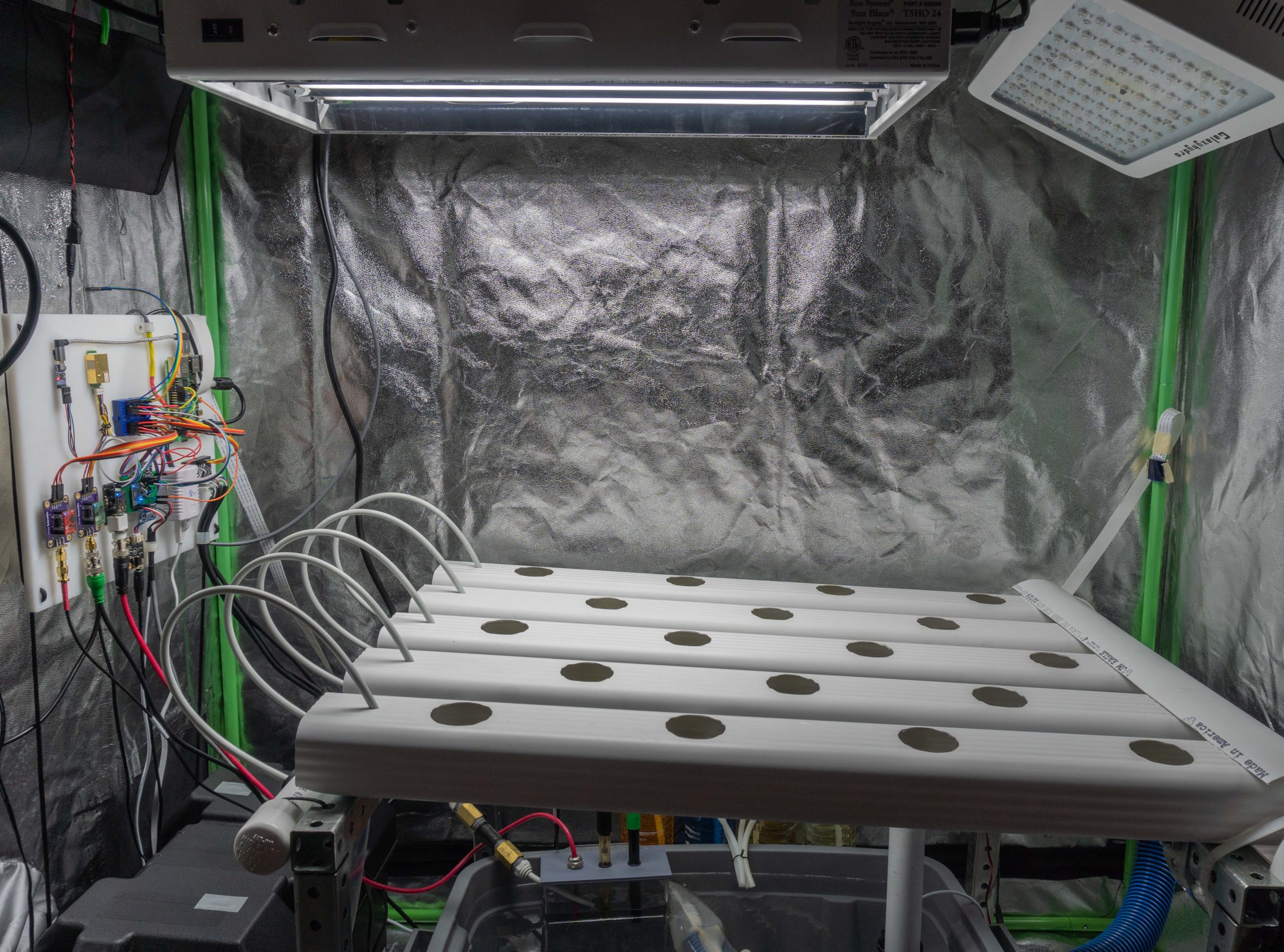
I won’t spend much time discussing specific types of lighting, as this is out of the scope of this article and there are already numerous resources devoted to this. If growing outdoors with good sun exposure, you usually won’t need any additional lighting, unless you desire a nursery for seedlings or to extend growing hours beyond sunset. However, if growing indoors, you’ll need at least one grow light. I’m using a Sun Blaze (T5HO 24) 96 Watt fluorescent fixture for germinating seeds and a Galaxyhydro (HYG05) 300 Watt LED fixture for the mature plants in the grow tent. I’ve also used both lights in combination in the grow tent.
The grow light puts off a lot of light and can result in poor photo quality. Since I want to capture photos with both a DSLR and Raspberry Pi camera, I needed a less bright and more neutral light source for illuminating the plants during photo acquisition. I also needed a way to turn off the grow light(s) while this secondary light was active and the photos were acquired. Although this will be covered in detail in the automation configuration, briefly, the following is how this was achieved. First, two simple outputs were created, one that controlled the switching of a light for taking photos, named Photo Light, and another that controlled the switching of the grow light, named Grow Light. Next, a Python Command Output was created, named Grow Light On Only, which executes user-defined Python commands when turned On and Off, with the On action executing code to turn Photo Light off and Grow Light on, and the Off action executing code that turns Grow Light off. Next, a Python Command Output was created, named Photo Light On Only, with the On action executing code that turns Photo Light on and Grow Light off, and the Off action executing code that turns Photo Light off and Grow Light On Only off.
To understand how this works, I’ll describe how the light timer works and explain the order of operations when photos are acquired. There are two timers that are used in order to keep Grow Light on only during the chosen grow period (e.g. 6 AM to 8 PM). The first is a duration timer, that at a regular period (e.g. every 15 seconds) between 6 AM and 8 PM, will set Grow Light On Only on, if it is not already on. This will cause Photo Light to turn off and Grow Light to turn on. A second timer (a single time point timer) will set Grow Light On Only off at 8:01 PM, which will turn Grow Light off. This covers keeping the Grow Light on during the grow period.
Now, the photo captures can be configured. My DSLR camera has a remote shutter cable that I wired to two outputs to activate the focus and to activate the shutter (auto focus is turned off, but this is still required by the remote shutter device to allow the shutter to actuate). I created a function that will switch the focus output, wait 1 second, then activate the shutter output, effectively causing the camera to take a photo. This function was set to repeat every 2 hours, which for a 24-frame per second video would equate to 1 second of video for every 2 days of photos. To make only the Photo Light active during the photo, I simply added the code to turn Photo Light On Only on before the code to capture the photo, and code to turn Photo Light On Only off after the code to capture the photo. When Grow Light On Only is turned on initially by the duration timer at 6 AM, only Grow Light is on. When Photo Light On Only is turned on by the time-lapse function, Photo Light is turned on and Grow Light is turned off. This provides a neutral white light for the photo. After the photo has been captured, turning Photo Light On Only off turns both Photo Light off and Grow Light On Only off (which means now no lights are on). Since the grow light timer checks every 15 seconds whether Grow Light On Only is on, and only if it’s off will it turn it on, Grow Light On Only will now be turned on, causing Grow Light to turn on.
This allows a single output (Photo Light On Only) to control the state of two lights, so that only one of them is permitted to be on at any given time. The Raspberry Pi camera was set up the same way to use this light configuration, by actuating the Photo Light On Only output on before photo acquisition and off after acquisition.
Building the Automation Hardware
We’ve just finished building a basic hydroponic system that can be manually operated and monitored. Next, we’ll build the capacity for automated growing by expanding on this base system. The automation hardware is essentially everything added to the base hydroponic system that will allow autonomous monitoring and control. This includes the sensors for air, water, and power measurements, peristaltic pumps, and power control box that will modulate fans, lights, humidifier, or other devices.
Control Panel
A central location is needed for all the hardware components to interface together to the Raspberry Pi, which will orchestrate the automation processes. Weatherproof enclosures are preferred, but for this build, I chose to use 0.375-inch thick high-density polyethylene (HDPE) plastic panel to mount everything. This is a very rigid material that is easily cut with hand or power tools. Cut the panel to 12 in. x 10 in. and lay all the components on the board to experiment with different layout configurations until you find one that works well. Here are a few things to consider when developing a layout:
- Wire lengths should be minimized to reduce the likelihood of introducing excessive noise or voltage-drop.
- Cables should be secured to the panel to prevent wires from being pulled out or excessive strain on connections (unless the connector is designed for that purpose, such as BNC, SMA, etc.).
- Avoid complex wire routing that makes following or understanding circuits difficult.
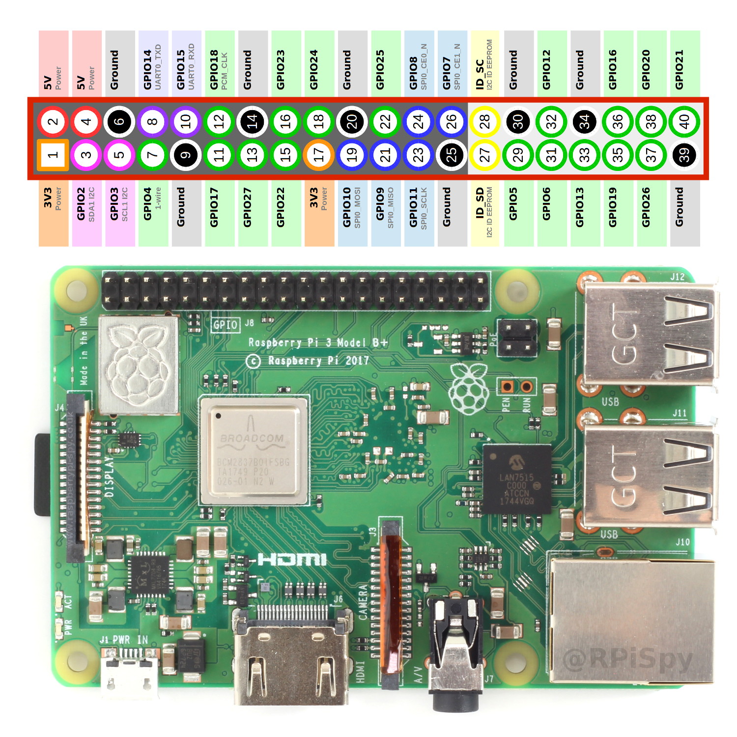
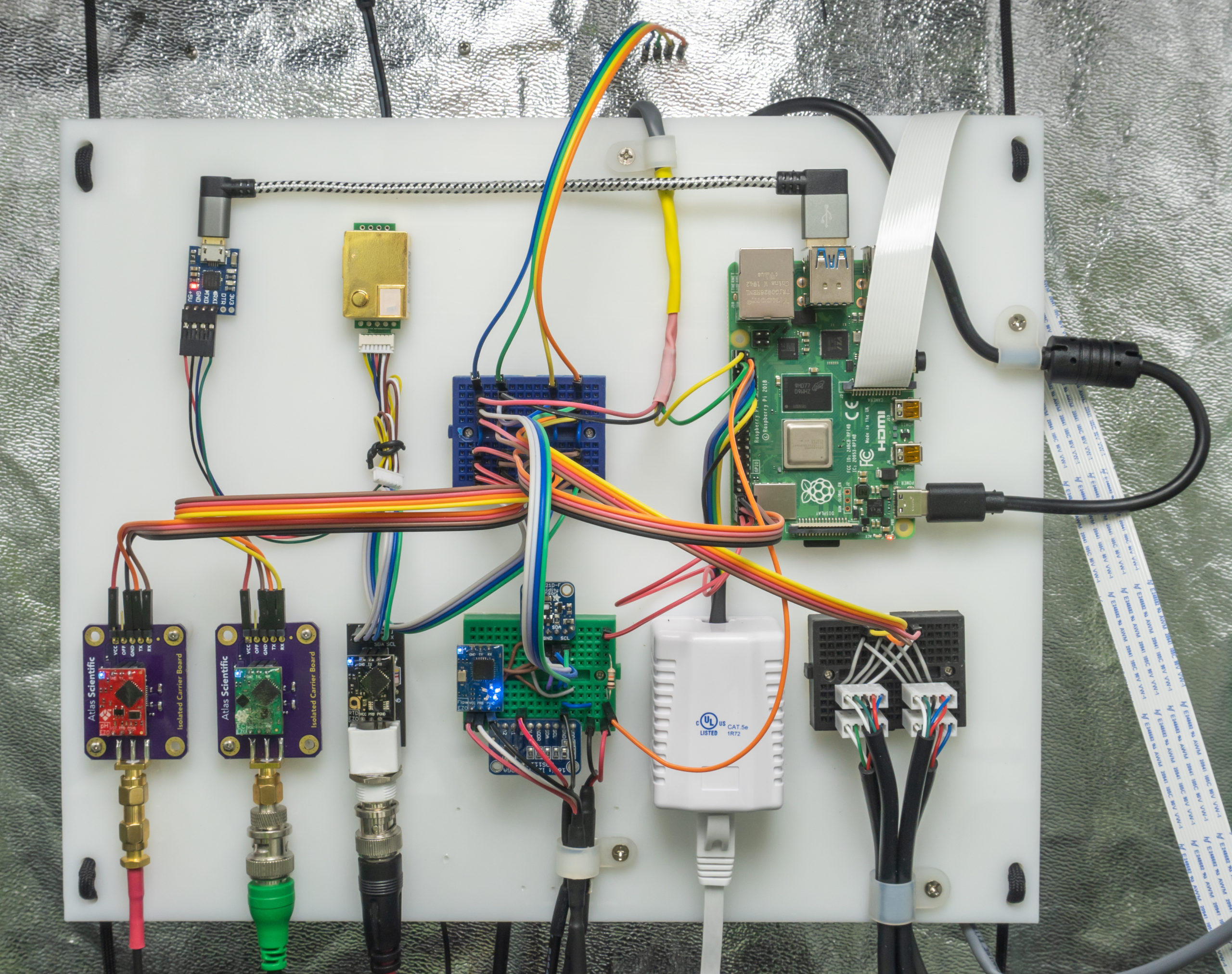
Start by connecting components with jumper wire. Below is a diagram of the Raspberry Pi and all pin designations on the 40-pin header, including ground pins, 3.3 and 5 volt pins, communication protocol pins, and the general purpose input output (GPIO) pins.
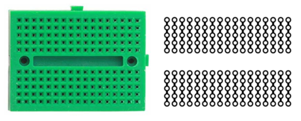
Solderless breadboards are used in this build to create many of the connections. A breadboard essentially allows us to rapidly prototype by being able to easily make and break connections. The contact points of a breadboard are connected by terminal strips to allow us to connect to a row of pins for easier access to connections if we desire multiple wires to be connected together. However, in a production setting you should use a board with screw terminals or a PCB to solder to for more secure connections.
The sections below describe how to connect the components, which should aid in developing the layout of the board. Once a good layout has been determined, place and secure the components to the board. Mark the mounting holes for each component on the board, then use an appropriate sized drill bit and screw to mount the component. For most of the components I used, a 1/16-inch drill bit with 7/16-inch #1 screws were sufficient. Spacers may be needed to mount some of the boards in a raised position, in order to prevent damage to components on the underside of the circuit boards if they come into contact with the mounting surface. For components without mounting holes, such as the CO2 sensor, double-sided tape or zip-ties can be used to secure the USB cable and the sensor to the board. Last, drill two larger holes near each corner so the board can be secured to two lengths of rope hung from the grow tent frame, which will allow easy adjustment in any direction on the wall.
Connecting the Sensors, LCD, and Pump
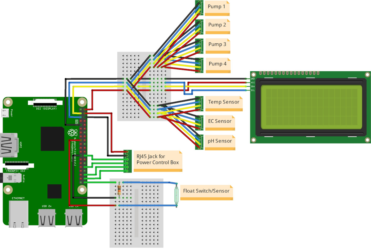
The sensors, LCD, and pumps will all connect to the same four pins of the Raspberry Pi to enable communication. These are the ground pin, 5-volt pin, serial data (SDA) pin, and serial clock (SCL) pin. These SDA and SCL pins represent the Inter-Integrated Circuit, or I2C, bus, which was designed for short-distance communication with sensors and devices. Connect the ground, 5-volt, SDA, and SCL pins from the Raspberry Pi to a breadboard so each connection is broken out into its own terminal strip, allowing multiple devices to be connected to these pins on the breadboard. For the number of devices we’ll be connecting, you will need to use male-to-male jumper wires to further break out these 4 pins to as many terminal strips as needed to connect all devices (I ended up needing to use 2 mini breadboards to connect all devices). Then, connect the sensors, LCD, and peristaltic pump communication lines to these connections of the breadboard(s).
The CO2 sensor components listed on the Material’s List need RX <-> TX, TX <-> RX, power, and ground to be connected from the sensor to the UART-to-USB board. The board can then be connected to the USB port of the Raspberry Pi and can be accessed at /dev/ttyUSB0 (use this device later in the software configuration).
The figure below is not an exact replica of the control board I built, but merely serves as an example of how to break out the I2C lines to connect all your devices. For a more accurate schematic, click here.
Note 1: Make sure all your I2C components are 3.3-volt compatible. Never allow 5 volts to be connected to any Raspberry Pi GPIO pin or the device or Raspberry Pi can be damaged. All I2C devices mentioned here can operate on 3.3-volts, but if you need to use a 5-volt device on the I2C bus, it’s best practice to use a
Note 2: In the schematics, you may notice I have all my I2C devices connected together and powered by 5 volts. There is only one circumstance when it is safe to do this, and that is if none of your devices pull SDA or SCL high to 5 volts with a resistor. Since none of the circuits of my I2C devices do this, it is safe to power them with 5 volts, since SDA and SCL are only pulled low for communication (1, 2). This is done because, although most of my I2C devices are both 3.5- and 5-volt compatible, my LCD only operates on 5 volts. Rather than connect a level shifter for just the LCD, I chose to just use 5 volts for everything. If using this method, be sure you do not inadvertently allow 5 volts to pass to SDA, SCL, or any other GPIO pins of the Raspberry Pi.
Note 3: Atlas Scientific sensors and pumps are set by default to the UART communication mode, not the I2C communication mode. You will need to refer to the datasheet provided by Atlas Scientific for each device to manually switch each device to I2C mode before being able to communicate with them on the I2C bus. This is a simple procedure that involves making a single connection on the sensor board and then powering it for a few seconds. For example, see page 41 of the Temperature sensor EZO circuit board datasheet for how to manually switch from UART to I2C mode.
Note 4: If mounting the air temperature and humidity sensors to the control panel, make sure to position the panel where the sensors are at the same height or slightly higher than your plants. If there isn’t vigorous mixing of air by fans, this is where a temperature and humidity gradient may form (with hotter air above this level). To yield the most accurate temperature and humidity regulation at location of your plants, the sensors should be positioned among or right above your growing plants.
Connecting the Float Switch
The float sensor is a magnetic switch encased in a rigid body, with two wires. A buoyant ring containing a magnet slides up and down this body, causing the switch to open or close the circuit depending on the water level. For the Raspberry Pi to use the float sensor to detect when the water level is high or low, a simple circuit needs to be created that yields either a high voltage (3.3 volts) or low voltage (0 volts) when the switch if open or closed. A GPIO pin on the Raspberry Pi can then be set as an input and measure this signal.
Briefly, to construct this circuit, connect a GPIO pin, a ground pin, and a 3.3-volt pin from the Raspberry Pi to their own terminal strips on a breadboard. Pull the GPIO connection on the breadboard low by connecting the GPIO terminal strip to the ground terminal strip using a 10 kΩ resistor. Last, connect one end of the float switch to the GPIO terminal strip and the other end to the 3.3-volt strip. Below is a minimal schematic of the circuit.
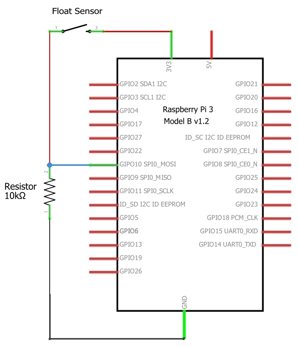
When the water level is low and the buoyant ring isn’t in proximity to the magnetic switch, the circuit is open (disconnected) and the GPIO pin is connected to ground and will measure 0 volts (low). When the water level is high and the magnet actuates the switch, the circuit is closed (connected) and the GPIO will be connected to the 3.3-volt pin and will measure 3.3 volts (high). When the circuit is closed, ground and 3.3-volts is connected by the 10 kΩ resistor that limits any current to a safe amount. When we monitor the GPIO pin, we can determine the water level based on whether the signal being measured is low or high. Note that either a pull-up or pull-down resistor can be used to change the voltage of the circuit when the water level is high or low. By changing this, either water level state can yield either a high or low signal. It does not matter which is used, as the software can be configured either way.
Connecting the RJ45 Surface Mount Jack
The power control box will allow the Raspberry Pi to independently control the power of four AC outlets with four relays. The control box will connect to the control panel by an RJ45 (Ethernet) surface mount jack, which will then connect to ground, 5-volt, and four GPIO pins on the Raspberry Pi. These connections will power and trigger four relay modules in the power control box, with each GPIO pin switching each relay. Make sure each connection of the RJ45 jack corresponds to the proper connection at the other end in the power control box. You can use the continuity setting of a multimeter to test each connection at both ends to ensure they’re connected. The ground and 5-volt pins of the Raspberry Pi should connect to GND and VCC of the relay modules, respectively, and each GPIO to each channel of each relay module. Once the power control box is constructed, a short Ethernet cable can connect the RJ45 jack on the control panel to the RJ45 connector on the power control box.
Liquid Solution Dispensing
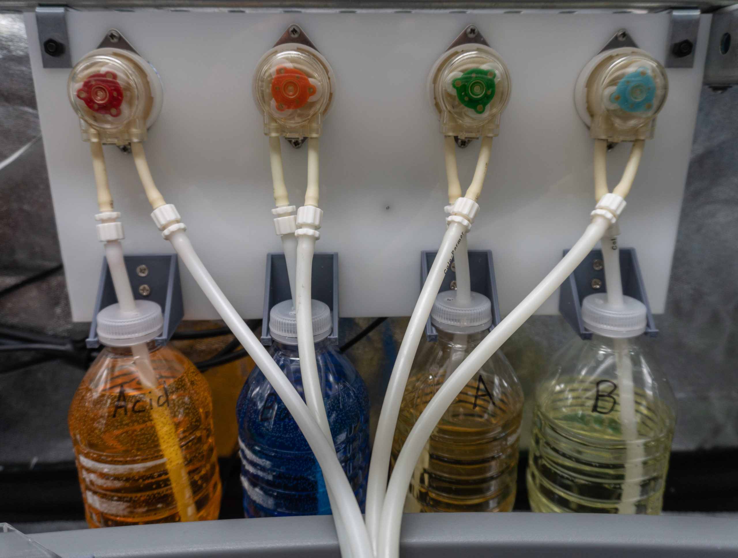
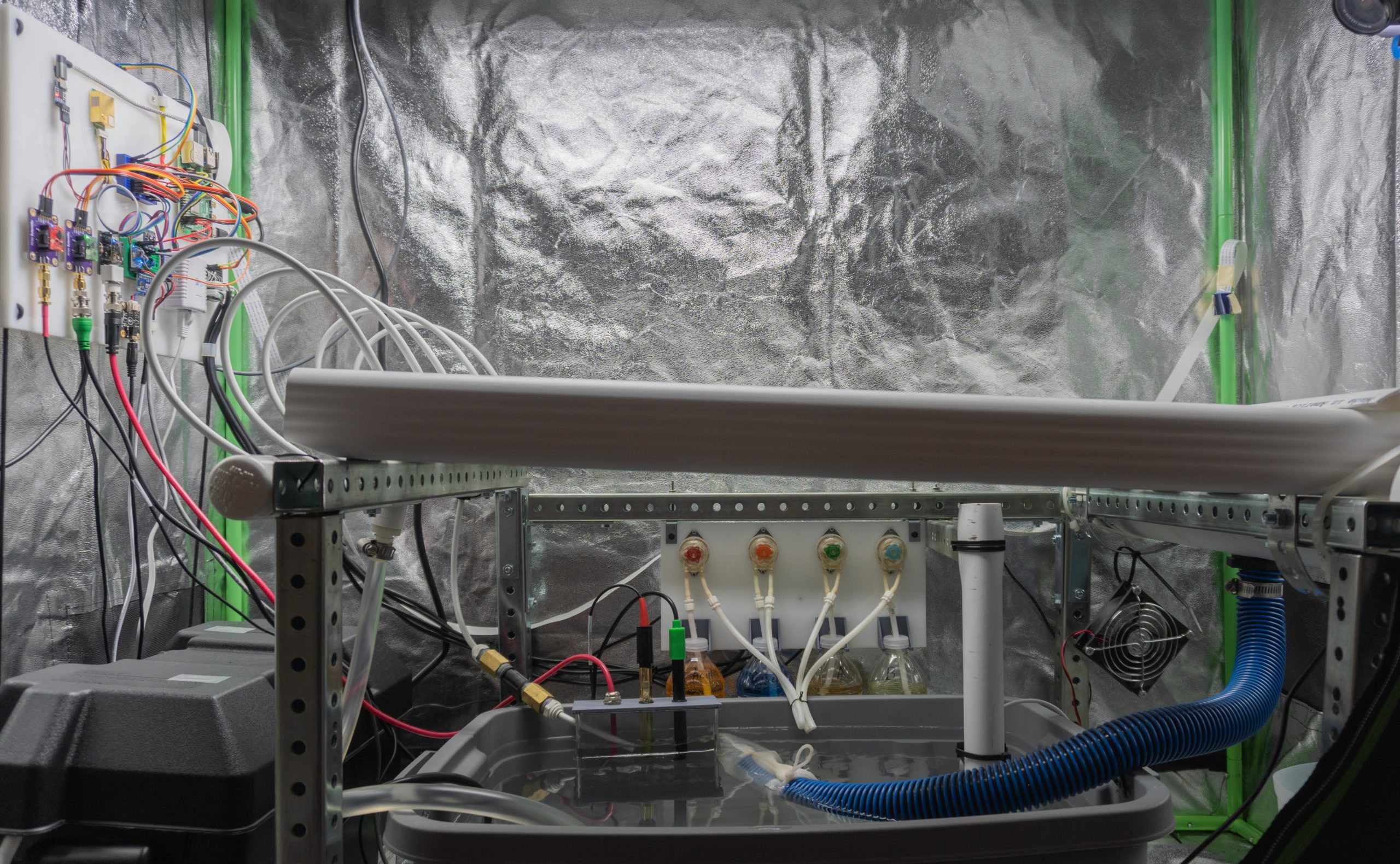
Four peristaltic pumps will be used to adjust the water chemistry by dispensing small amounts of acid (lowers pH), base (raises pH), and nutrient A and B solutions (raises electrical conductivity). The pumps need to be located close to the water reservoir to reduce hose length and have enough room to accommodate four solution tanks below the pumps. I found the back horizontal bar (spine) of the frame to be an ideal mounting point.
Cut another piece of HDPE panel to 12 in. x 6 in. that the pumps and solution reservoirs will be mounted to. I modeled and 3D-printed mounts to hang a 12-ounce plastic bottle under each pump, but your bottles can rest on the ground or by some other mounting option. Position the pumps and mounts, mark their mounting holes on the panel, then drill 1 1/4-inch holes for the pumps to extend through the panel and smaller holes for securing the pumps to the panel. To connect the 12-volt DC power supply to the pumps, solder 4 sets of negative and positive wires together, respectively, and connect them to the appropriate negative and positive screw terminals of the female barrel connector that the power supply male barrel connector will plug into. Then, connect each set of 12-volt wires to each pump’s power screw terminals. Last, the tubing needs to be installed to pump fluid from the bottles to the reservoir. Drill a hole into each bottle lid, then connect 5 mm tubing to each pump input and feed it to the bottom of each bottle. Last, cut four more lengths of tubing, connect them to the output lines of the pumps, then a zip-tie them all together over the reservoir.
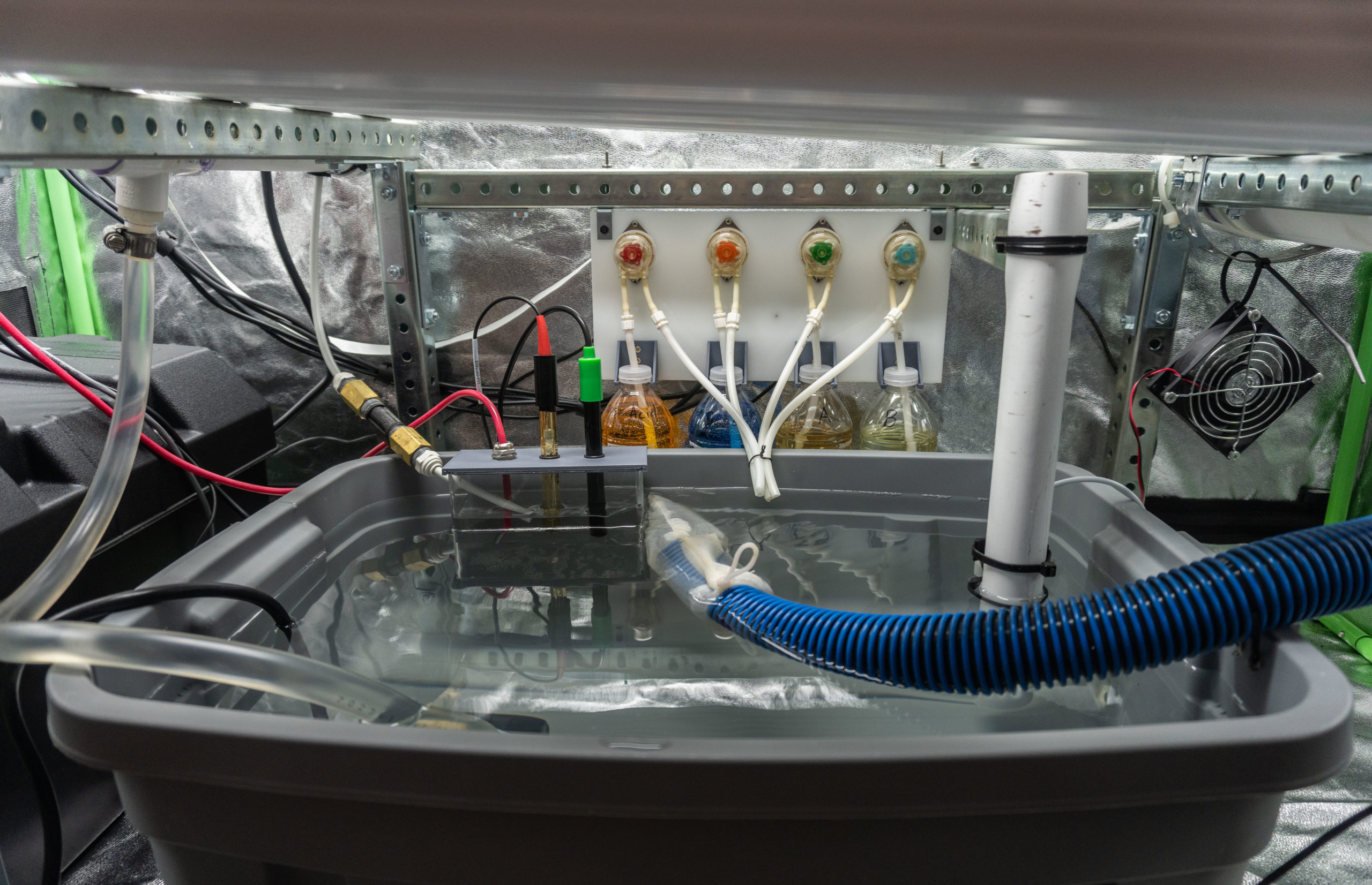
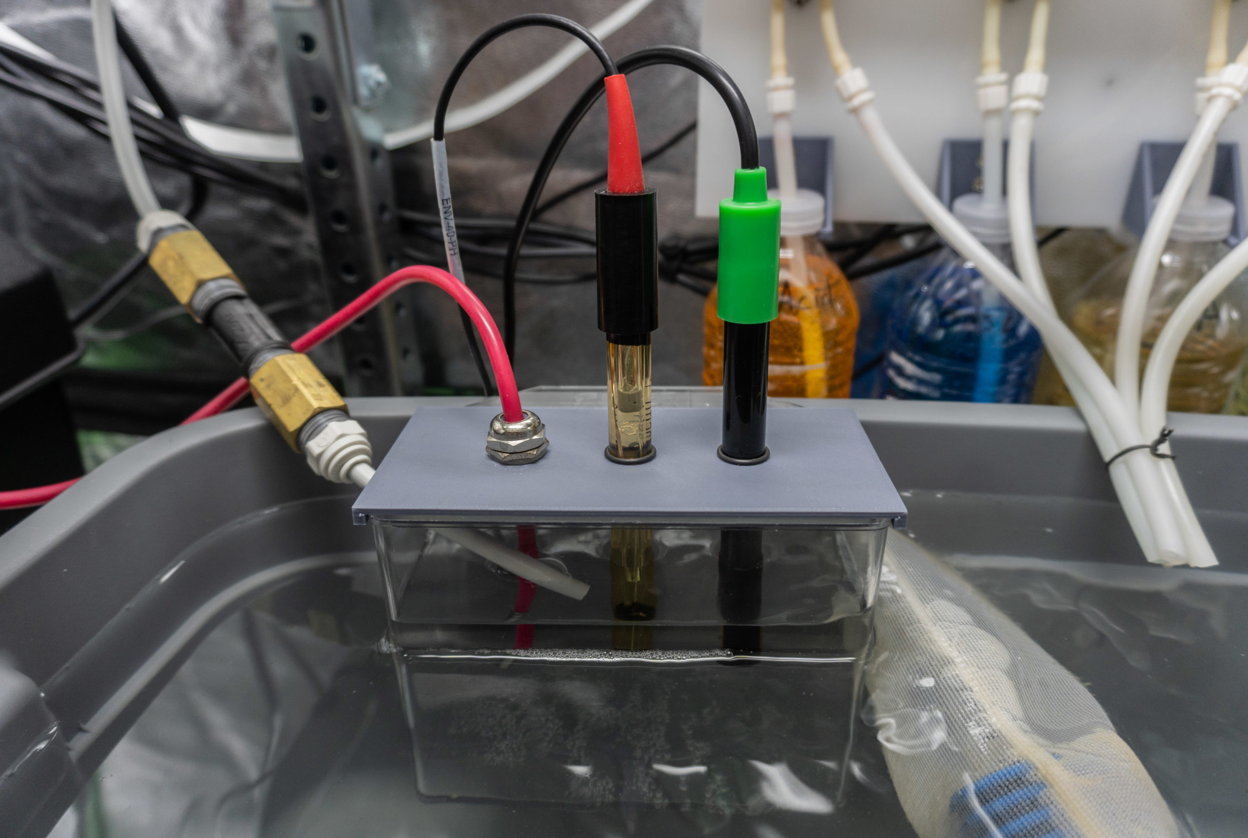
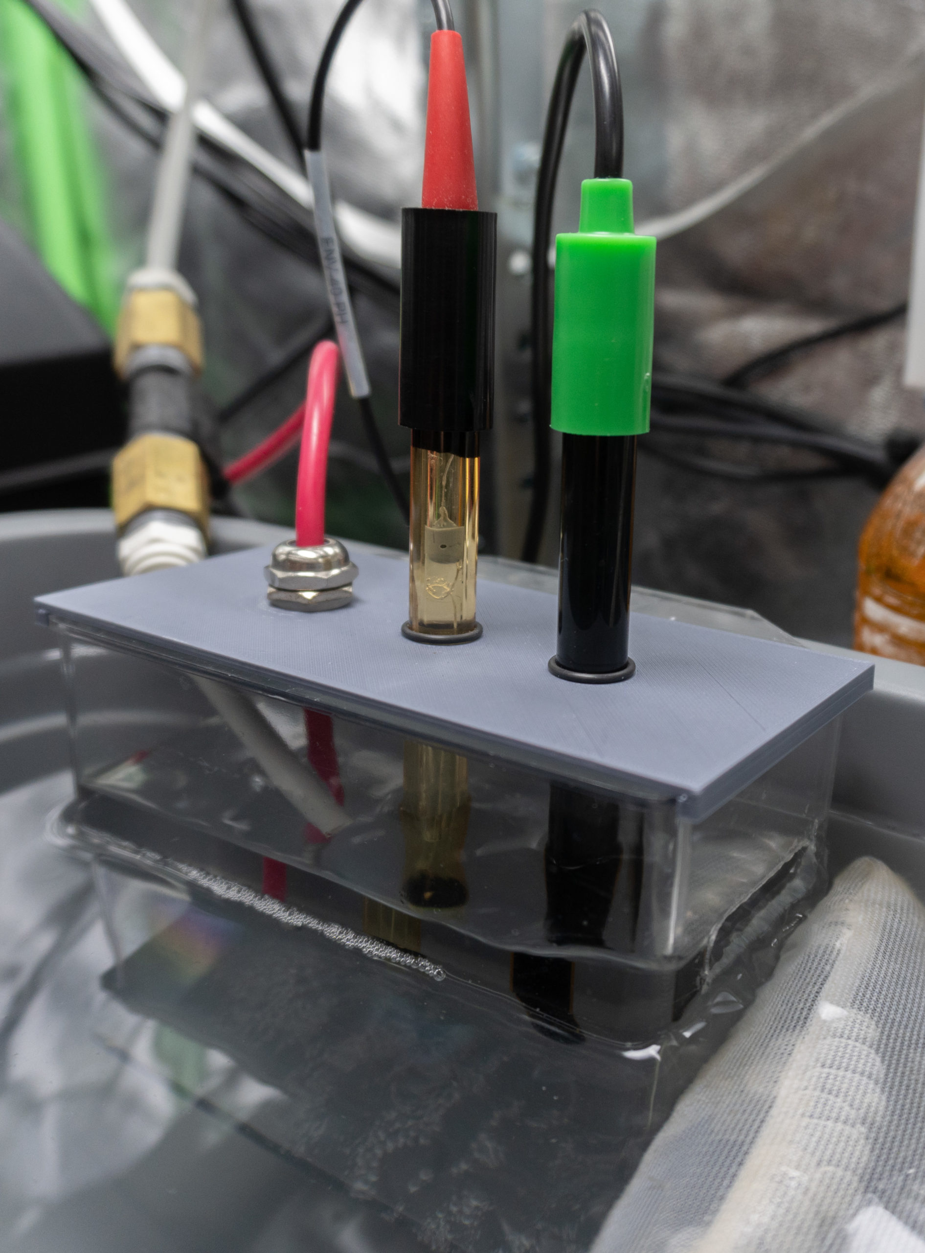
Sensor Sample Reservoir
A sample reservoir was constructed to divert a small volume of water from the main reservoir for the water sensors to measure. This is done in order to sub-sample the main water reservoir, which will buffer our sensors from the immediate effects of large pH and electrical conductivity swings that can occur in the main reservoir when the pumps are dosing solutions.
For the sample reservoir construction, I modeled and 3D printed a lid that fits on the top of the sample reservoir to hold the temperature, pH, and electrical conductivity probes. However, drilling holes in a flat piece of plastic or zip-tying the probes to the side of the sample reservoir would also work. Rubber gaskets were slid onto the EC and pH probes to prevent them from sliding all the way into the holes and allowing their height in the fluid to be adjusted. These probes will need to always be submerged in water, so inflow and outflow holes need to be added to the sample reservoir. Ensure the outflow hole is sufficiently large so water can exit the reservoir faster than it enters. Drill an outflow hole or slot on the side of the sample reservoir 2 to 4 inches above the bottom of the highest sensor probe. Drill a 1/4-inch inflow hole near the top of the sample reservoir, on the side opposite side of the outflow hole. Since the plastic material is fragile, I used a Dremel to cut the inflow and outflow holes rather than using a drill bit. Secure the sample reservoir near the water inlet PVC pipe connected to the water pump. Make sure the water pump is turned off, then drill a 3/8-inch hole in the inlet PVC pipe near the sample reservoir. Place a microtube grommet in this hole, then attach a microtube from the grommet to the sample reservoir. Turn the water pump back on and ensure there are no leaks and the water fills the sample reservoir before spilling back into the main reservoir.
Water Flow Sensing
A water flow meter can be easily installed to the water line feeding the sample reservoir, and is useful for detecting if the pump is operating properly (and notifying you when it is not). After applying thread seal tape to the flow meter, screw push-to-connect fittings to both ends of the flow meter with couplings. Cut out a section of the microtube feeding the sample reservoir that’s the length of the flow meter, then press the microtube ends into the push-to-connect fittings. Last, connect the three wires of the flow meter to the Atlas Scientific Flow Meter Totalizer on the control panel.
Electrical Current Sensing
In order to measure the amount of electrical current being consumed by the system, we’ll use a transformer to measure one wire of the main alternating current (AC) power cord that powers the system, upstream from any devices that are plugged in. The transformer will convert the AC current proportionally to a DC voltage. This DC voltage will then be converted to a digital signal with an ADS1115 analog-to-digital converter connected to the Raspberry Pi. Using this voltage, the Mycodo software will then be able to calculate the amount of current that’s consumed over time, in Amps. This can be further used by Mycodo to automatically calculate the monetary cost to operate over periods of time (day, week, month, year, or custom dates) and based on your local cost per kWh.
To do this, we’ll need to isolate a single wire in our power cord. I sacrificed a 1-foot extension cord rather than cutting into my power strip cord. Cut away a few inches of the external insulation of the extension cord, being careful not to cut into the insulation of the individual wires. This exposes single wires to clamp the transformer around. Depending on which current sensor used from the Material’s List, there are two ways to connect the sensor.
The spit-core transformer is easier to use because it can clamp around a wire, however it is less accurate than a solid-core transformer. If using the split-core transformer, open it and close it around the live wire. From there, connect the output connector from the transformer to the current sensing board. Last, connect the negative and positive DC voltage outputs from this board to the analog-to-digital converter’s Ground and Analog 0 Input (A0) connections, respectively.
A solid core transformer is more accurate than a split-core transformer, but it requires feeding a wire through the core or cutting and feeding a wire through the core before soldering the wire back together. First, ensure the cable is not plugged in. If using the solid core transformer, cut the live wire, strip their ends, and feed one end through the solid-core transformer. Solder the wire ends back together with the transformer still surrounding the wire and use heat-shrink tubing to cover the solder joint. last, connect the negative and positive DC voltage outputs from the transformer to the analog-to-digital converter’s Ground and Analog 0 Input (A0) connections, respectively.
Power Control Box
The power control box will allow the 3.3-volt DC signals from the Raspberry Pi GPIO pins to safely switch AC devices, such as grow lights, exhaust fans, humidifiers, or other devices.
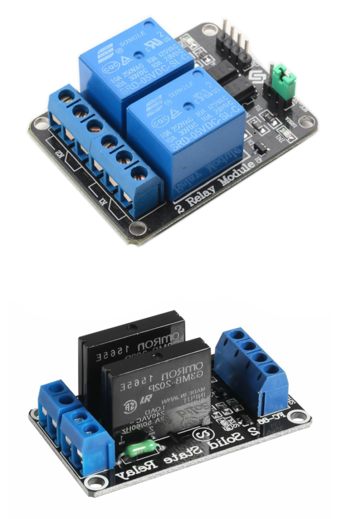
To understand how this works, here’s a brief introduction to how the two main types of relays operate. Mechanical relays use a small input voltage to energize electromagnets that cause the physical movement of metal contacts in the output component of the relay that turns on and off much larger voltages. Solid state relays (SSRs) use a small input voltage to produce a light that shines across an air gap to energize a sensor that switches the output connections. Mechanical relays make an audible “click” sound when tuning on and off, and compared to SSRs, are less expensive, can typically handle higher electrical currents, but have a lower life expectancy, with a mean time before failure (MTBF) in the several hundred hours range. Solid state relays are silent when turning on or off, can handle lower currents, but have a high life expectancy, with a MTBF in the several million hours range (yes, million, with some as high as 40 million or more, which equates to 4566 years, under ideal conditions). Although this is not always true, as relays of course vary in their specifications, it does illustrate the general differences.
I typically use mechanical relays for operations that require high current loads and slow switching, such as grow lights that only turn on or off a few times a day. I typically use SSRs for applications that may need to switch much faster, such as heating and humidity control (several switches per minute) or pulse-width modulation (PWM) signal generation (several switches per second). Although mechanical relays can often handle many applications (please don’t try PWM), increasing their rate of switching can increase their chance of failure (and be annoying as heck to hear their constant clicking). When possible, I try to only use SSRs because of their superior reliability.
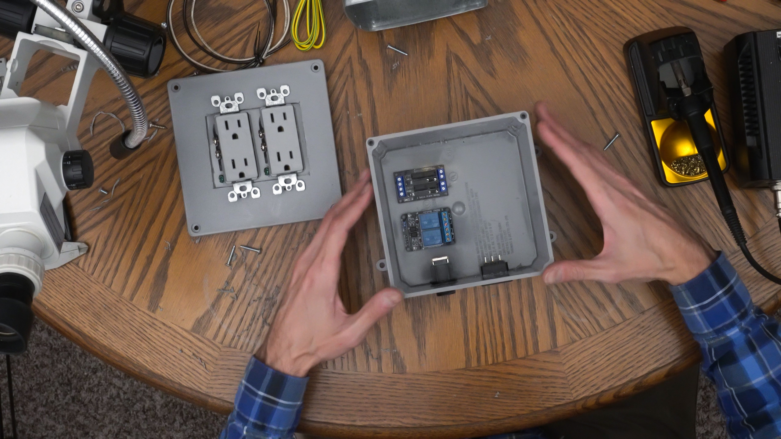
For these reasons, I built my power control box with two mechanical relays to handle slow-switching, high-current devices (grow lights), and 2 SSRs to handle fast-switching, low-current devices (exhaust fan and humidifier). Always adhere to the current limitations of your relays and don’t plug in any devices that could exceed 10 Amps for the mechanical relays or any that could exceed 2 Amps for the SSRs (or whatever the specific current ratings are for your particular relays). Since alternating current is dangerous, I’m protecting the circuitry and relays in a 6 x 6 inch junction box.
Start by placing two sets of outlets and their cover on the junction box lid and mark where the main opening for the outlets will be. Remember to leave space for the mounting holes to secure the outlets to the lid and to use the outlet cover to ensure you’re adequately spacing the outlets. Cut the main opening in the junction box lid, drill the mounting holes, and dry-fit the outlets. On the junction box, mark the holes that needs to be cut for the panel mount power socket and the panel mount RJ45 connector near the bottom of the box. Cut each hole and dry fit each part.
Next we’ll wire everything. Inside the junction box, the panel mount power socket will have 3 blade terminals, for neutral, ground, and live (diagram below). Use 14 or 16 gauge wire for all connections involving AC power, and either crimp female blade connectors or solder the wires directly to the power socket connections. I recommend using heat shrink tubing to cover all exposed AC connections. Follow the wiring instructions and diagram, below, for wiring the remaining connections.
- Connect G (ground) from the power socket to the green ground connector of each outlet.
- Connect N (neutral) from the power socket to the neutral connector of each outlet.
- Connect L (live) from the power socket to one of the two output connectors for every relay (i.e. every relay output will control a live connection to an outlet).
- Each remaining output connector from each relay will connect to the live connector of each outlet.
- One Ethernet wire to the ground (-) input of each relay module.
- One Ethernet wire to the positive (+) input of each relay module.
- One Ethernet wire to the channel 1 signal input of the mechanical relay.
- One Ethernet wire to the channel 2 signal input of the mechanical relay.
- One Ethernet wire to the channel 1 signal input of the solid state relay.
- One Ethernet wire to the channel 2 signal input of the solid state relay.
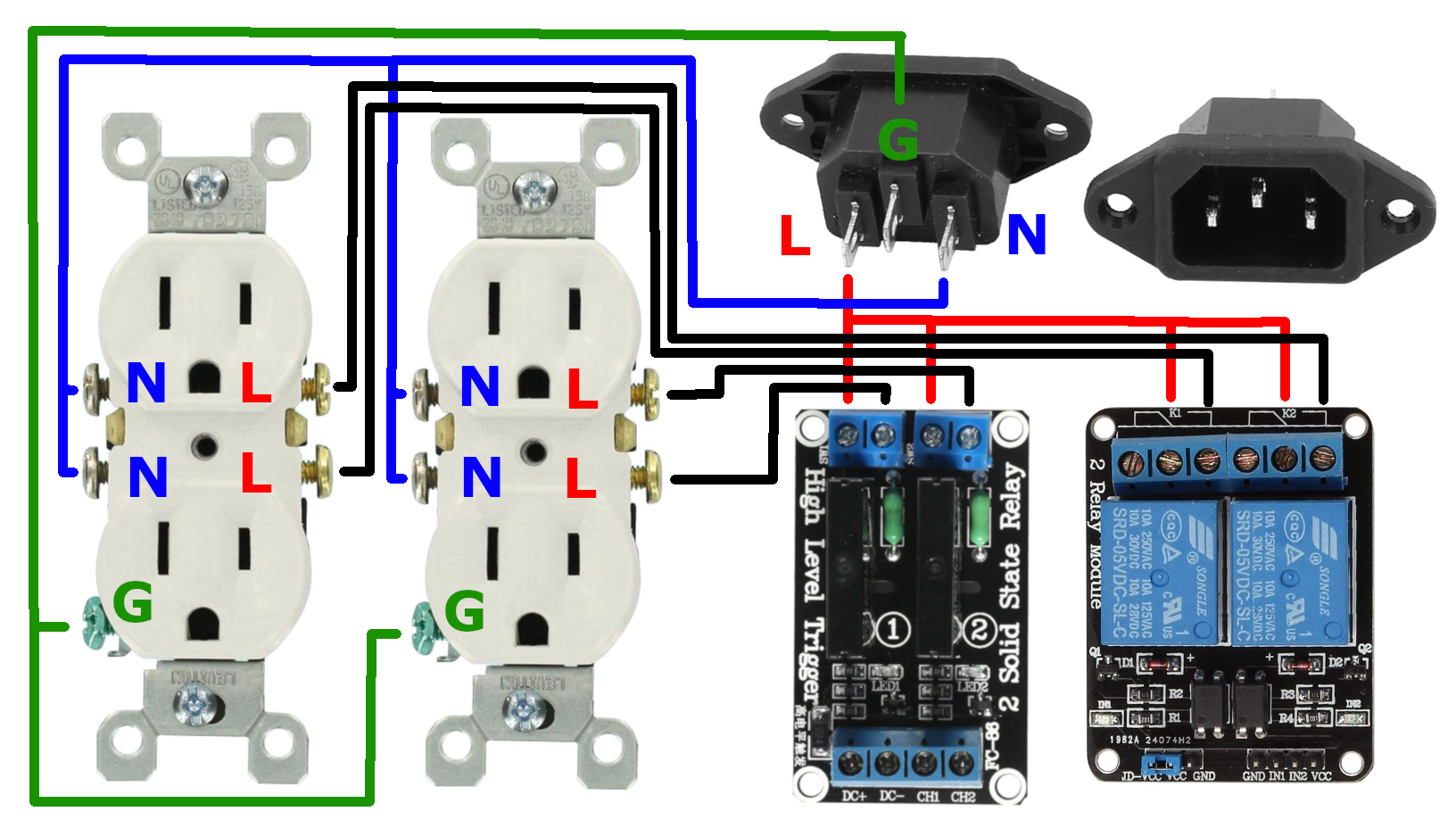
Note: many outlets have a metal tab that connects both outlets to the same circuit (one tab for neutral, one tab for live), which can be broken off on each side. When unbroken, this allows one set of wires to power both outlets. Since we want to power each outlet independently, the live tab needs to be broken off with pliers. The neutral tab can remain intact, allowing you to connect only one neutral that will be distributed to both outlets. The diagram, above, has been drawn with the assumption there are no tabs present.
Warning: If you leave the live side tab intact, both outlets will be powered when either live wire is energized by either relay. The live tab must be broken to independently control each outlet. If you don’t break the tab, you will be potentially powering two devices instead of one when the relay actuates, potentially exceeding your relay’s maximum current.
Each relay will have output screw terminals that will be used to switch the AC power. Wire the power socket’s live connection to one of these output screw terminals for each relay. if there are 2 connections, it doesn’t matter which, so long as it’s connected to only one of the two relay output terminals. If there are 3 connections, connect to the normally-open (NO) connections so the power is off when the relay is not active. Next, connect the second output screw terminal of each relay to the live connector of each outlet. This will allow the live connection of each outlet to be switched by each relay. You should mark which outlets are connected to mechanical relays and which are connected to SSRs.
Now connect the signal wires to the relays from the RJ45 connector inside the junction box. There are two ways to do this: A) cut a small length of raw Ethernet wire and crimp a connector on one end, or B) cut a consumer Ethernet cable leaving a short length on the end. This will give you an Ethernet cable with a connector on one end that will plug into the RJ45 connector inside the box. The other end of the Ethernet cable should have 6 of the 8 wires stripped for connecting to the relay modules. Be sure to note the color of the wires and what they’re connected to. Since there are two relay modules, the wires you designate for ground and positive will have to connect to the ground and positive of both relay modules. Much like the outlets, you can run the ground wire to the mechanical relay’s ground screw terminal (typically labeled “GND” or “DC-“), then run a short wire from that same screw terminal to the other relay’s ground connector. Since the SSR has only male header pins, you can simply cut and strip a jumper wire with a female header to make this connection. Do the same for the positive connection (typically labeled “VCC” or “DC+”). For the four relay input signal connections (typically labeled “CH#” or “IN#”, with # denoting the channel number), you will need to use four wires from the Ethernet cable. Connecting to the screw terminals is straightforward, but to connect to the SSR input signal male header pins, you will have to either crimp or solder jumper wires with female headers to the Ethernet wires.
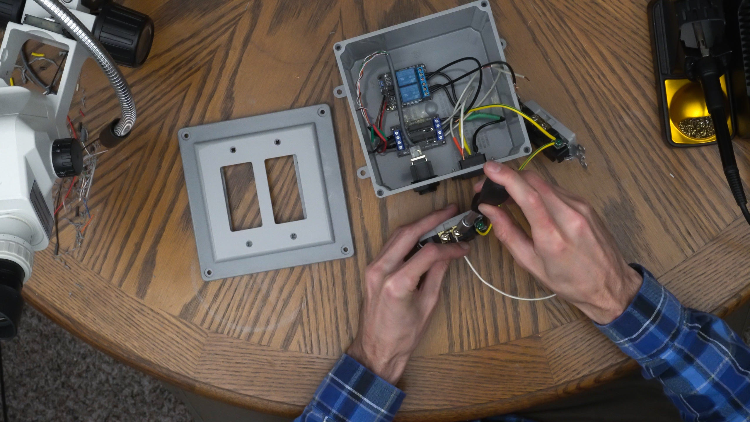
Once all the connections have been made, screw the relay modules to the bottom of the junction box using spacers and screws, screw the lid to the junction box, screw both outlets to the lid, then screw the face plate over the outlets. Connect an Ethernet cable from the external RJ45 port of the control box to the RJ45 surface mount jack of the control panel. We now have a power control box that can independently control the power to four outlets using a common Ethernet cable.
WARNING: Always be ready to quickly disconnect power when testing electrical devices you built yourself for the first time. No one likes to see smoke come from their hardware, but excessive damage can sometimes be avoided by quickly removing power.
Of course, if you want to buy a commercial version of a power control box like this instead of building it,
This concludes the hardware section of the build process and getting the hydroponic system ready to be automated with the Mycodo software. Read on to learn how to install the Raspberry Pi operating system on your Raspberry Pi and install and configure Mycodo to automate the system.
Installing and Configuring the Automation Software
Install Raspberry Pi Operating System
Now that we have a functioning hydroponic system and all our electrical hardware has been set up, we can install the operating system and Mycodo and begin configuring the system to run autonomously.
You should always follow the latest instructions for installing Mycodo, on GitHub, as this will be where the most up-to-date instructions can be found.
As of this article’s writing, briefly, you will need to install the Raspberry Pi operating system to a micro SD card by downloading the latest Raspberry Pi OS Lite Image, then use one of the recommended flashing tools (Etcher or the new Raspberry Pi Imaging Tool) to burn it to your micro SD card. Once the image has been flashed, you should see one of the SD card partitions recognized by your computer, labeled “boot”. Create a blank file in this boot drive named “ssh” (with no file extension). This will allow the ability to connect to the Raspberry Pi via a secure shell (SSH) connection after booting it for the first time. Also, if you would like your Raspberry Pi to automatically connect to your WiFi router, create another file on the boot drive named “wpa_supplicant.conf”. I recommend using a good text editor for this (such as Notepad++ or Sublime Text), as Windows notepad or other simple text editors often cause errors due to extra characters they create in the files. In “wpa_supplicant.conf”, add the following text, changing “NETWORK-NAME” to your WiFi’s network name and “NETWORK-PASSWORD” to your WiFi’s password, then save.
country=US
ctrl_interface=DIR=/var/run/wpa_supplicant GROUP=netdev
update_config=1

network={
    ssid="NETWORK-NAME"
    psk="NETWORK-PASSWORD"
}
Insert the micro SD card into your Raspberry Pi, then plug in the power. After a minute or so, it should be connected to your WiFi. Alternatively you can connect it to your router with an Ethernet cable. Now, you will need to find the IP address of your Raspberry Pi that’s connected to your network. This can often be done by logging into your router and viewing the devices that have connected through DHCP, which should show a device named “raspberry”. Note the IP address of your Raspberry Pi. Since multicast DNS is supported by the Raspberry Pi OS, you might also be able to reach your Pi at the address raspberry.local. Open a terminal or command prompt and type ping raspberry.local and if you get a response, you’ll find your Raspberry Pi’s IP address. More information about other methods to find your Raspberry Pi’s IP address can be found here.
Next, start up your favorite terminal. Linux and Mac already have terminals you can use for this, but if on windows, I recommend Putty. If on Linux/Mac, open a terminal and use the command ssh pi@192.168.0.50 replacing “192.168.0.50” with the IP address of your Raspberry Pi that you noted earlier. Putty requires settings the host to pi@192.168.0.50 and port to 22 to connect. You should be prompted for a password, which by default is “raspberry”. Once logged in, you should be looking at a terminal with a flashing cursor at the end of pi@raspberry:~ $
Before installing Mycodo, it is recommended to use the command sudo raspi-config and change the default password to something more secure, set the time zone, set the wifi country, then reboot for the changes to take effect. More information about raspi-config can be found here.
Install Mycodo
Now we can install Mycodo. Again, always follow the latest instructions for installing Mycodo, on GitHub. As of the writing of this article, it is a single command that is entered in the terminal:
curl -L https://kizniche.github.io/Mycodo/install | bash
It will take a few minutes for Mycodo to install. Once complete, the text on the terminal will display the web address to use to access the web user interface (UI). Open a web browser to this address and you will be greeted with a screen to create a new administrator user, then the login page.
Port Forwarding
If you would like to access Mycodo from outside your local network, you will need to log in to the modem/router that your Raspberry Pi is connected to and forward port 443 to your Raspberry Pi’s IP address. This can be as simple as forwarding external port 443 to your Pi’s port 443, or you can forward a different port, such as 5000 to 443 if you want to access your Pi from an non-standard port. Keep in mind the modem/router that your Raspberry Pi is connected to will need to be connected to the internet for this to work. Once forwarded, you should be able to access your Raspberry Pi from anywhere with internet by visiting your modem’s IP address. Your modem’s IP can be found by visiting whatsmyip.com while connected to your home network. If your modem’s IP address is 122.22.22.22, and port 443 was forwarded to port 443 of your Raspberry Pi, you can simply open a browser to https://122.22.22.22 (notice the s in https), however, if port 5000 was forwarded to port 443, then you would specify the port and navigate to https://122.22.22.22:5000.
If your IP address changes, you won’t be able to connect from outside your network until you find what the new IP address is. This is where dynamic DNS can provide you a hostname that will point to your IP address, and will update when your IP address changes. This allows you to connect, for instance, to https://mypi.dyndns.org and be assured it will always forward to your modem’s current IP address. Check out freedns.afraid.org for free dynamic DNS services.
Configuring Mycodo
While following this guide, keep in mind that Mycodo is constantly being updated and what’s documented here may deviate from what can be found in the latest version of Mycodo you may have installed. Therefore, if you notice any discrepancies, it’s recommended to first refer to the Mycodo Manual (also available as PDF, HTML, and TEXT) before seeking support elsewhere.
Adding and Configuring Inputs
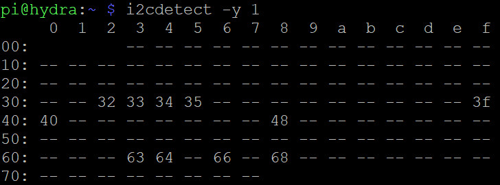
After logging in, ensure all inputs that are connected by I2C are detected by the operating system. To do this, you can either execute the command i2cdetect -y 1 in a Raspberry Pi terminal or navigate to the Configure -> System Information page on the Mycodo web UI and find the section “I2C Bus”. You should see an address for each I2C device or sensor that’s connected (figure, below).
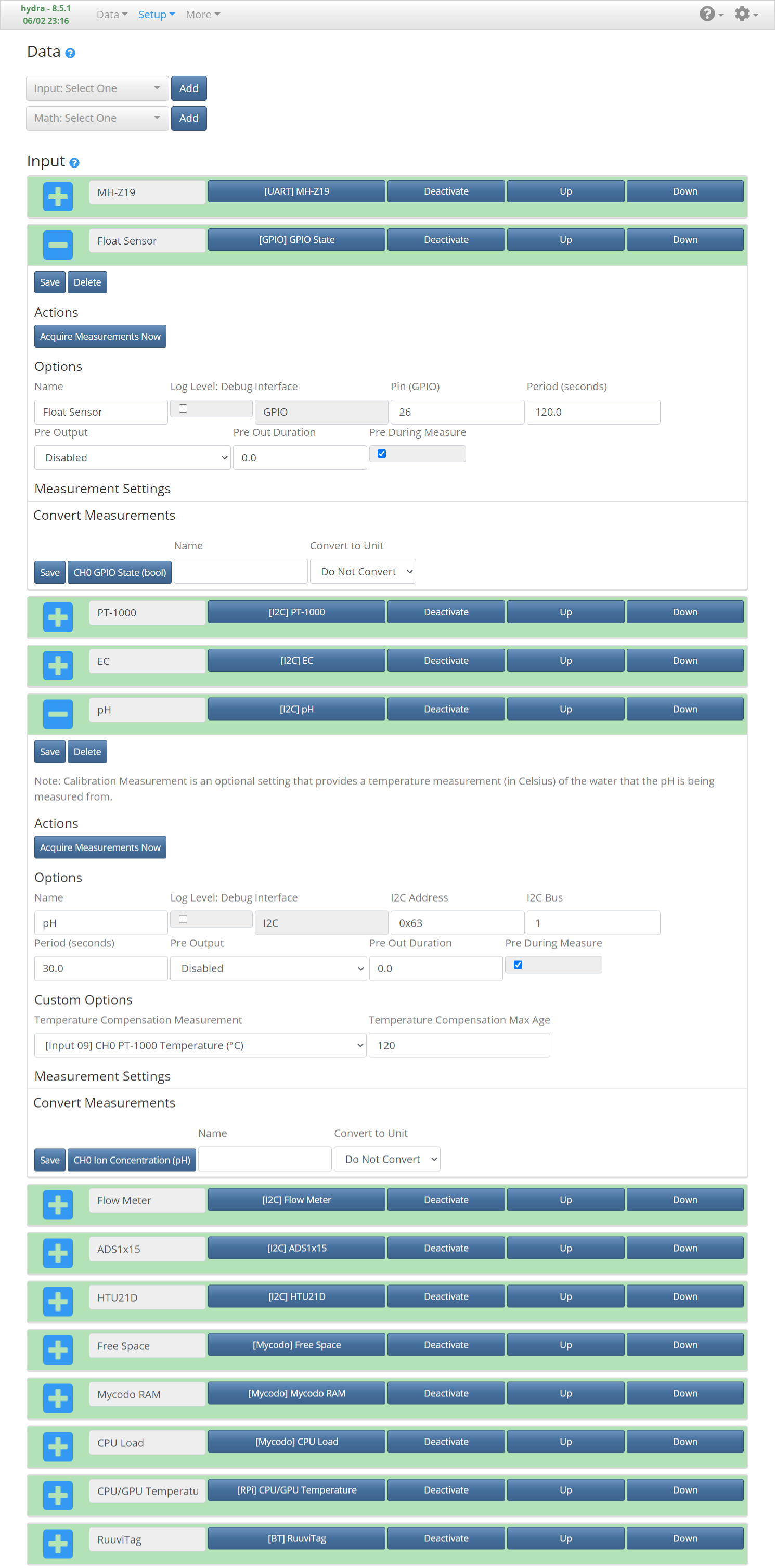
Navigate to the Setup -> Data page and use the drop-down menu to search for each of your sensors and add them. The default configuration options are usually okay to use, however some inputs may need additional configuration prior to activation:
- If using the ADS1115 analog-to-digital converter, the voltage that’s measured will need to be converted to Amps. If using the clamp transformer and current sensor board listed in the Materials list, you’ll need to set your ADS1x15 Input options as follows: Unscaled Unit Max to 2 (volts), Rescaled Unit Max to 20 (amps), and Rescaled Measurement to “Electrical Current: Amp (A)”. If using the Greystone current sensor listed in the Materials List, switch the transformer’s switch to L and set your ADS1x15 Input options as follows: Unscaled Unit Max to 0 (volts), Rescaled Unit Max to 10 (amps), and Rescaled Measurement to “Electrical Current: Amp (A)”.
- For the Water Flow Input, you’ll need to set the Flow Meter Type to “Atlas Scientific 3/8″ Flow Meter”.
- For both the Electrical Conductivity and pH Inputs, set the Temperature Compensation Measurement to the Atlas Scientific PT-1000 temperature, which will improve accuracy by calibrating each sensor to the temperature of the water prior to acquiring measurements. Note: The PT-1000 Input will have to be created before it will be available for selection in other configuration menus.
- For the MH-Z19 sensor, if using the UART-to-USB board, set the Input’s UART Device to “/dev/ttyUSB0”.
- To set up the Input for the float sensor, add a “GPIO State” Input, then set Pin (GPIO) to the GPIO pin you used when the float sensor circuit was made, previously.
Review the rest of the Input options, then activate your Inputs.
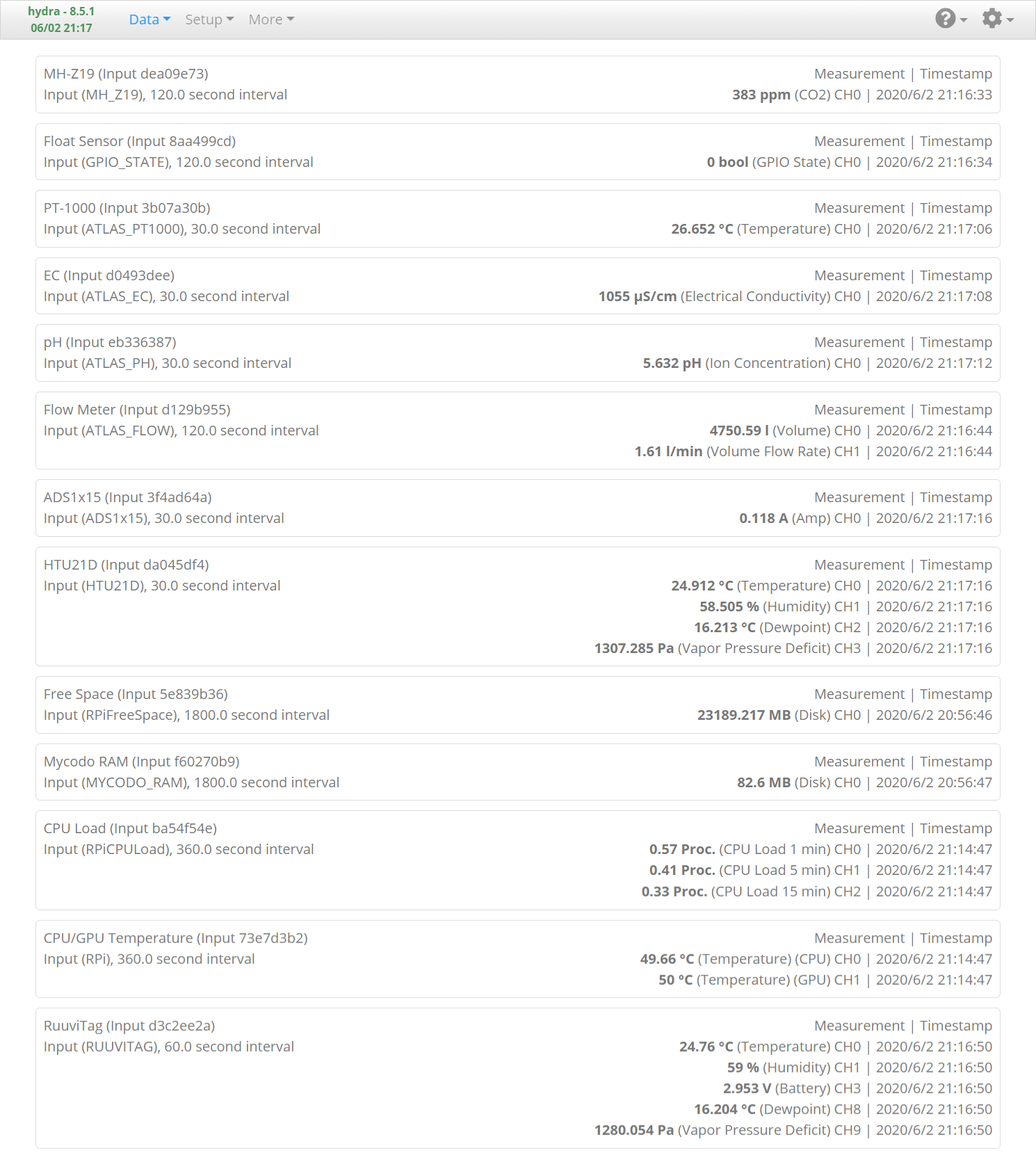
You can then verify measurements are being successfully recorded by navigating to the Data -> Live page (figure, below).
Adding and Configuring Outputs
First, ensure all Atlas Scientific peristaltic pumps have been changed to I2C mode. Additionally, all pumps come from the factory set to the same I2C address by default, but are able to be changed with a simple command. If multiple pumps with the same address were to be connected at the same time, we wouldn’t be able to communicate with them individually. Therefore, we’ll first need to set each pump to a unique I2C address before they can be used independently by Mycodo. First, disconnect all pumps from the Raspberry Pi’s I2C bus. Then, start the Atlas Scientific I2C script in a terminal with the following command:
~/Mycodo/env/bin/python ~/Mycodo/mycodo/devices/atlas_scientific_i2c.pyNext, use the “List_addr” command to list the I2C addresses of the connected devices. Connect one of the pumps and execute the command again to determine which address the pump is using. The pump should be using 0x63 by default, which as an integer is 100 (and is how the script should list it). Use the command “Address,100”, to start communicating with address 100. Now, you can issue the command “I2C,50” to change the address of the pump to 50 (0x32). Repeat the procedure with all four pumps, using a unique and unused address for each pump. Since the addresses 0x63, 0x64, 0x66, and 0x68 are in use by other devices, we can’t use 4 consecutive address next to the default address, so I chose to use 0x32 (50), 0x33 (51), 0x34 (52), and 0x35 (53) for my four pumps. Once all pumps have had their address changed to unique addresses, you can plug them all in at the same time, verify you’ve successfully changed their addresses, and continue with their setup.
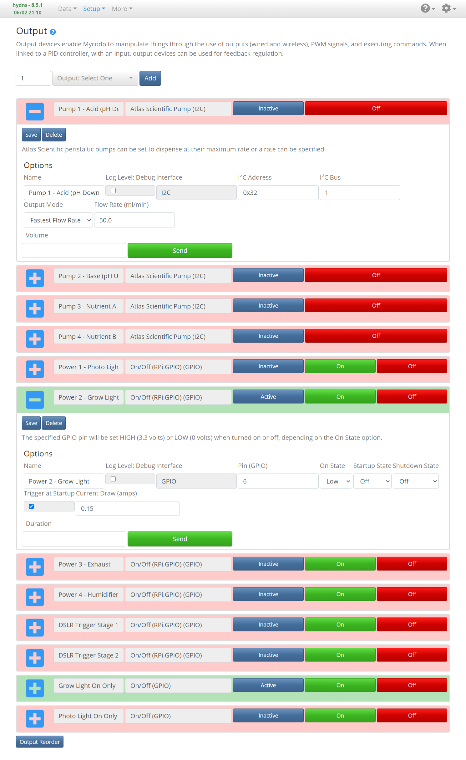
Navigate to the Setup -> Output page and add four “On/Off (GPIO)” and four “Atlas Scientific Pump (I2C)” outputs. Set the Pin (GPIO) for each On/Off output (see the Raspberry Pi pin map image, above) to the pins you connected your control box signal wires to earlier. Then, test whether the outputs works by plugging in a device, such as a lamp, and clicking On for the corresponding output. Set up each pump by setting the proper I2C Address you set for each pump earlier, using the hex format (e.g. 0x32, 0x33, etc.). Then, test that each pump dispenses when you instruct it to dispense a volume.
In line with the previously-mentioned light setup, I named my grow light output Grow Light. This is all you need to do for the output configuration for your light, if you have a simple light configuration that you only desire to control one outlet (which can have one or several lights attached to). If a second light is desired to create more neutral light for automated photography (time-lapse), add the additional light outputs, below.
Create “On/Off (GPIO)” output named Photo Light and set the GPIO pin connected to the relay controlling the output with the light used to take photos plugged in. Create an On/Off (Python Command) output named Grow Light On Only, and set the On Command to to following, changing the IDs to correspond to the IDs of your Photo Light and Grow Light outputs:
# photo light off
control.output_off('PHOTO_LIGHT_ID', output_channel=0)
# grow light on
control.output_on('GROW_LIGHT_ID', output_channel=0)
Set the Off Command to to following, changing the ID to correspond to the ID of your Grow Light output:
# grow light off
control.output_off('GROW_LIGHT_ID', output_channel=0)
Create an On/Off (Python Command) output named Photo Light On Only, and set the On Command to to following, changing the IDs to correspond to the IDs of your Photo Light and Grow Light outputs:
# photo light on
control.output_on('PHOTO_LIGHT_ID', output_channel=0)
# grow light off
control.output_off('GROW_LIGHT_ID', output_channel=0)
Set the Off Command to to following, changing the IDs to correspond to the IDs of your Photo Light and Grow Light On Only outputs:
import time
# photo light off
control.output_off('PHOTO_LIGHT_ID', output_channel=0)
time.sleep(1)
# grow light only off
control.output_off('GROW_LIGHT_ON_ONLY_ID', output_channel=0)
This allows the Grow Light to be the only light on when Grow Light On Only is turned on, then Photo Light On Only can be used to turn Grow Light off and Photo Light on during photo acquisitions. For a more detailed description of the use of these functions, see the Lighting section of this publication.
Calibration
The peristaltic pumps as well as the pH and electrical conductivity sensors may require calibration before they operate accurately. Mycodo has built-in functions for calibrating all of these devices, and provides an easy walk-through guide to instruct you at each step of the way to calibrate them. Navigate to the More -> Calibration & Setup page and select which device you want to calibrate, then follow the instructions. Note: Inputs being calibrated will need to be deactivated prior to beginning calibration. Briefly, the steps for calibrating each device are as follows.
The peristaltic pump calibration entails priming the tubing to remove all air, then instructing the pump to dispense a calibration amount, such as 10 ml. Measure how much fluid was actually dispensed (e.g. 9 ml), and input this value when prompted by the Mycodo calibration. The pump will now accurately dispense volumes and can be verified by instructing it to dispense a volume from the Setup -> Output page and verifying it actually dispenses that amount. Make sure to calibrate all peristaltic pumps.
The pH sensor calibration will require either two or three calibration solutions. A three-point calibration will yield higher accuracy than a two-point calibration, but two is still better than none. These solutions should be at 4, 7, and 10 pH. The probe should be placed in each solution and allowed to acclimate before the calibration to each standard pH solution is carried out. Rinse the probe with distilled water before being placed into the next solution. The calibration steps are repeated until all solutions have been used to calibrate.
The electrical conductivity sensor will require two calibration solutions. Enter the values of the solutions when prompted, then insert the probe in the first solution and instruct Mycodo to calibrate to that solution. Rinse the probe with distilled water and repeat for the second solution.
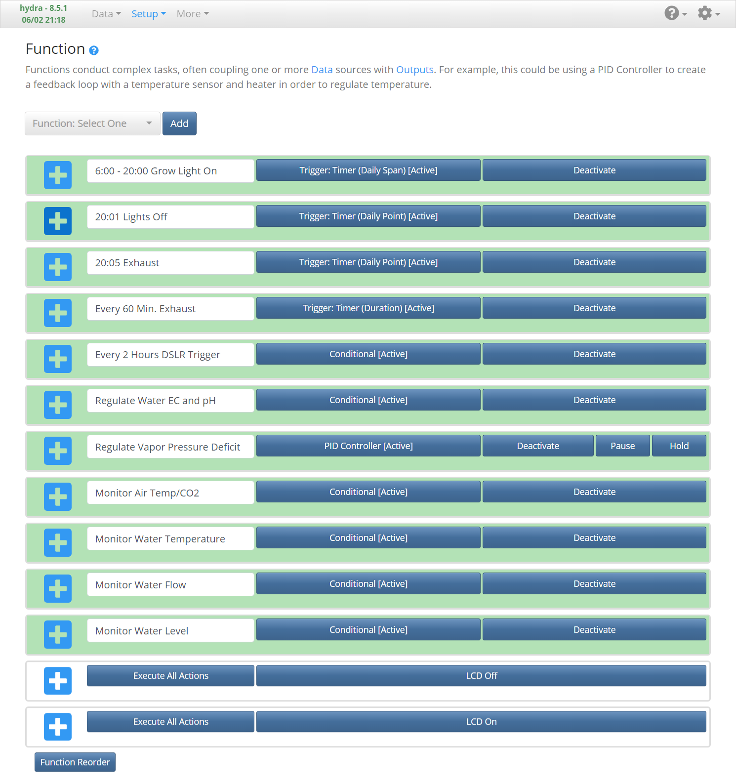
Adding and Configuring Functions
Navigate to the Setup -> Function page, where several functions will be created that will automate the system. They include:
- Timer to turn on a grow light from 6 AM to 8 PM.
- Function to regulate electrical conductivity and pH with the peristaltic pump outputs.
- Function to regulate vapor pressure deficit with a humidifier and exhaust fan.
- Function to monitor air and water temperature, water level, or other important measurements and alert by email if they fall out of acceptable ranges.
- Timer to periodically exhaust air.
- Other functions for your application (e.g. I’m using a timer to trigger my DSLR camera to capture photos for a high quality time-lapse).
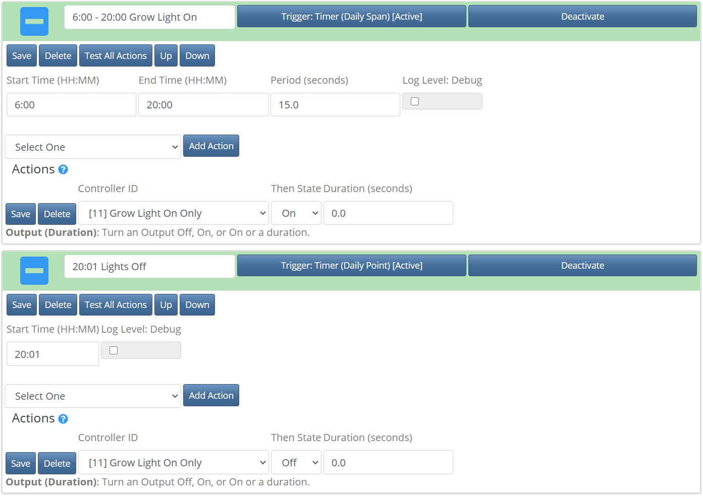
Grow Light Schedule
Add “Trigger: Timer (Daily Span)” and “Trigger: Timer (Daily Point)” functions. For the Daily Span Timer, add an “Output (Duration)” Action, then configure the Output by selecting your Grow Light Output, setting State to “On”, then save. Next, set the Start Time to “6:00” and End Time to “20:00”, then save. For the Daily Point Timer, also add an “Output (Duration)” Action, and set the Output to your Grow Light Output and State to “Off”, then save. Next, set the Start Time to “20:01”, then save. Activate both controllers and your grow light output will remain on between 6 AM and 8 PM and turn off at 8:01 PM. If using a Photo Light output, select the Grow Light on Only output instead of the Grow Light output.
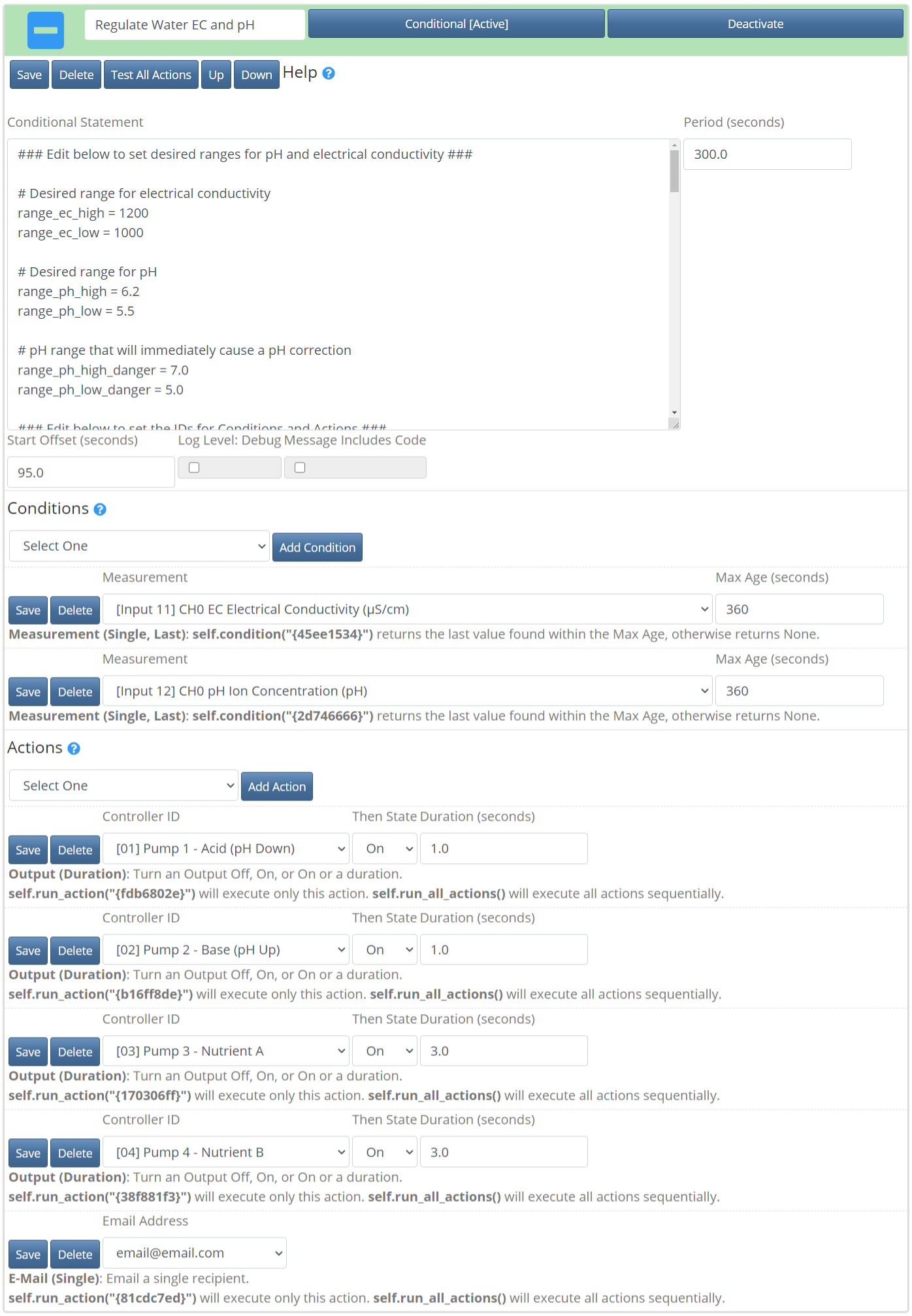
Electrical Conductivity and pH Regulation
Add a “Controller: Conditional” function. Set the Period to “300”, then add two “Measurement (Single, Last)” Conditions, four “Output (Duration)” Actions, and one “Email (Single)” Action. Set one Measurement Condition to the pH measurement, and the other to the electrical conductivity measurement. Set the first Output to the first pump, with the State “on” and the Duration “1”, which will dispense the acid. Set the second Output to the second pump, with the State “on” and the Duration “1”, which will dispense the base. Set the third Output to the third pump, with the State “on” and the Duration “3”, which will dispense the nutrient A. Set the fourth Output to the fourth pump, with the State “on” and the Duration “3”, which will dispense the nutrient B. Last, set the Email Action to the email you would want to get alert notifications if the measurements aren’t working. Next, copy the following code to the Conditional Statement, changing “PH_MEASURE_ID” to the ID associated with the pH measurement, “EC_MEASURE_ID” to the ID associated with the electrical conductivity measurement, “IDpump1” to the pump 1 ID, “PUMP_2_ID” to the pump 2 ID, “PUMP_3_ID” to the pump 3 ID, “PUMP_4_ID” to the pump 4 ID, and “EMAIL_ID” to the email action ID. These IDs are found under each Condition or Action that was created earlier.
import time

### Edit below to set desired ranges for pH and electrical conductivity ###

# Desired range for electrical conductivity
range_ec_high = 1300
range_ec_low = 1000

# Desired range for pH
range_ph_high = 6.2
range_ph_low = 5.5

# pH range that will immediately cause a pH correction
range_ph_high_danger = 7.0
range_ph_low_danger = 5.0

### Edit below to set the IDs for Conditions and Actions ###

condition_id_measurement_ph_id = "PH_MEASURE_ID"  # Condition: measurement, last, pH Input
condition_id_measurement_ec_id = "EC_MEASURE_ID"  # Condition: measurement, last, EC Input
action_id_pump_1_acid = "PUMP_1_ID"  # Action: Pump 1 (Acid)
action_id_pump_2_base = "PUMP_2_ID"  # Action: Pump 2 (Base)
action_id_pump_3_nutrient_a = "PUMP_3_ID"  # Action: Pump 3 (Nutrient A)
action_id_pump_4_nutrient_b = "PUMP_4_ID"  # Action: Pump 4 (Nutrient B)
action_id_email_notification = "EMAIL_ID"  # Action: Email Notification

### DO NOT EDIT BELOW THIS LINE UNLESS YOU KNOW WHAT YOU ARE DOING ###

if 'notify_ec' not in self.variables:  # Initiate EC notification timer
    self.variables['notify_ec'] = 0
if 'notify_ph' not in self.variables:  # Initiate pH notification timer
    self.variables['notify_ph'] = 0
if 'notify_none' not in self.variables:  # Initiate None measurement notification timer
    self.variables['notify_none'] = 0

measure_ec = self.condition(condition_id_measurement_ec_id)
measure_ph = self.condition(condition_id_measurement_ph_id)
self.logger.debug(f"Conditional check. EC: {measure_ec}, pH: {measure_ph}")

if None in [measure_ec, measure_ph]:
    if measure_ec is None:
        self.message += "\nWarning: No EC Measurement! Check sensor!"
    if measure_ph is None:
        self.message += "\nWarning: No pH Measurement! Check sensor!"
    if self.variables['notify_none'] < time.time():  # Only notify every 12 hours
        self.variables['notify_none'] = time.time() + 43200  # 12 hours
        self.run_action(action_id_email_notification, message=self.message)  # Email alert
    return

# First check if pH is dangerously low or high, and adjust if it is
if measure_ph < range_ph_low_danger:  # pH dangerously low, add base (pH up)
    msg = f"pH is dangerously low: {measure_ph}. Should be > {range_ph_low_danger}. Dispensing 1 ml base"
    self.logger.debug(msg)
    self.message += msg
    self.run_action(action_id_pump_2_base)  # Dispense 1 ml base (pH up)
    if self.variables['notify_ph'] < time.time():  # Only notify every 12 hours
        self.variables['notify_ph'] = time.time() + 43200  # 12 hours
        self.run_action(action_id_email_notification, message=self.message)  # Email alert
elif measure_ph > range_ph_high_danger:  # pH dangerously high, add acid (pH down)
    msg = f"pH is dangerously high: {measure_ph}. Should be < {range_ph_high_danger}. Dispensing 1 ml acid"
    self.logger.debug(msg)
    self.message += msg
    self.run_action(action_id_pump_1_acid)  # Dispense 1 ml acid (pH down)
    if self.variables['notify_ph'] < time.time():  # Only notify every 12 hours
        self.variables['notify_ph'] = time.time() + 43200  # 12 hours
        self.run_action(action_id_email_notification, message=self.message)  # Email alert

# If pH isn't dangerously low or high, check if EC is within range
elif measure_ec < range_ec_low:  # EC too low, add nutrient
    self.logger.debug(f"EC: {measure_ec}. Should be > {range_ec_low}. Dosing 3 ml Nut A, 3 ml Nut B")
    self.run_action(action_id_pump_3_nutrient_a)  # Dispense 3 ml nutrient A
    self.run_action(action_id_pump_4_nutrient_b)  # Dispense 3 ml nutrient B
elif measure_ec > range_ec_high:  # EC too high, add nutrient
    msg = f"EC: {measure_ec}. Should be < {range_ec_high}. Need to add water to dilute!"
    self.logger.debug(msg)
    if self.variables['notify_ec'] < time.time():  # Only notify every 12 hours
        self.variables['notify_ec'] = time.time() + 43200  # 12 hours
        self.message += msg
        self.run_action(action_id_email_notification, message=self.message)  # Email alert

# If EC is in range, make sure pH is within range
elif measure_ph < range_ph_low:  # pH too low, add base (pH up)
    self.logger.debug(f"pH is {measure_ph}. Should be > {range_ph_low}. Dispensing 1 ml base")
    self.run_action(action_id_pump_2_base)  # Dispense 1 ml base (pH up)
elif measure_ph > range_ph_high:  # pH too high, add acid (pH down)
    self.logger.debug(f"pH is {measure_ph}. Should be < {range_ph_high}. Dispensing 1 ml acid")
    self.run_action(action_id_pump_1_acid)  # Dispense 1 ml acid (pH down)
Activate the controller and it will run the code every 5 minutes, which will check the pH and electrical conductivity and compare them to the first 6 variables which define the minima and maxima of the allowable ranges for pH and electrical conductivity. A pH “danger” range is first checked, which if the pH is outside this range, an email notification will be set and acid or base will be dispensed until the pH returns to within this range. Next, if the pH is within the danger range, but the pH is out of the normal range and the electrical conductivity is low, it will first add nutrients A and B at an equal ratio (1:1) in 3 ml increments until the electrical conductivity rises above the minimum that’s set. Only after the electrical conductivity is within the desired range will acid or base be added to bring the pH into the desired normal range.
These order of events were chosen because nutrients are typically acidic and will lower the pH when added. If nutrients were added after the pH was adjusted, the pH could be brought back out of the desired normal range and require readjustment. By adjusting the electrical conductivity first, this issue is avoided. The only exception is if the pH becomes so low or high that it falls outside the designated danger range, which will trigger an email notification and cause the pH to be immediately adjusted with acid or base until it falls back within the danger range. Once back within this range, electrical conductivity can be adjusted again. For instance, this prevents the pH from becoming dangerously acidic if a large amount of water is replaced in the system, requiring a large amount of nutrient solution to be dispensed to being the electrical conductivity back to the desired range. This large amount of nutrient solution will significantly lower the pH, which doesn’t usually occur under normal operating conditions, where small amounts of nutrients are added at a time. Another benefit of this is the email notification that the pH is found to be at an extreme, which could also indicate something is wrong with the system.
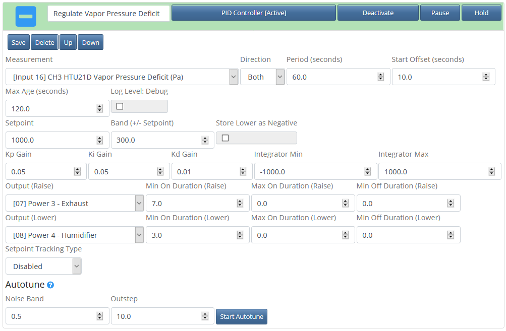
Vapor Pressure Deficit Regulation
To effectively adjust the vapor pressure deficit, a humidifier and exhaust fan is required. Essentially, we will change the vapor pressure deficit to an ideal range for plant health by either adding humidity with a humidifier or removing humidity and heat with an exhaust fan. Add a “Controller: PID” function, then set the following options: Measurement to “vapor pressure deficit” (this should be a measurement included with a temperature/humidity sensor), Direction to “Both”, Setpoint to “850”, Band to “350”, Kp Gain to “0.05”, Ki Gain to “0.05”, Kd Gain to “0.01”, Integrator Min to “-1000”, Integrator Max to “1000”, Output (Raise) to “Exhaust Output”, Min On Duration (Raise) to “5”, Output (Lower) to the “Humidifier Output”, and Min On Duration (Lower) to “5”. Save, then activate the controller.
Configure Email Notification/Alert Settings
For email notifications to work, you’ll have to first configure an email address that will be used to send the emails. Gmail is a good option, but you will have to Enable Less-Secure Apps for the account first. You may want to create a new Gmail address only to be used with sending Mycodo notification emails. Your email credentials should be entered on the Configure -> Alerts page. Once you have configured the required settings, enter your email address and click “Send Test Email” to test whether your settings worked.
There are many alerts that can be created to notify you by email when a measurement deviates from a set range, but I’ll document how to create two, and these examples can be used to create ones for other measurements. Of the notifications I’ve used, the most important are knowing when a measurement isn’t being acquired, which indicates a sensor issue, knowing when the water level is low so I can replenish the water reservoir, and knowing that the water and air temperatures are within an acceptable range.
Email Notification for Air Temperature
Add a “Controller: Conditional” function. Add the Condition “Measurement (Single, Last), and set it to the measurement you want to monitor (e.g. air temperature). Add the Action “E-Mail (Single)” and set it to the email address you will want to be notified. If you want to edit or add email addresses, this can be done from the user configuration menu. Copy the following code to the Conditional Statement, then replace “asdf1234” with the ID associated with your Measurement Condition, and “qwer5678” with the ID associated with your Email Action.
air_temperature_C_high = 35
air_temperature_C_low = 5

air_temperature = self.condition("{asdf1234}")

if air_temperature is not None:
    if air_temperature > air_temperature_C_high:
        self.message += "Air temperature is too high! ({} C) \n".format(air_temperature)
    elif air_temperature < air_temperature_C_low:
        self.message += "Air temperature is too low! ({} C) \n".format(air_temperature)
    else:
        return
    self.run_action("{qwer5678}", message=self.message)
else:
    self.message += "Cold not find an air temperature measurement. Check your sensor!"
    self.run_action("{qwer5678}", message=self.message)
The two variables at the top set the minimum and maximum allowed temperatures. If the measured temperature falls outside this range, a message is generated and emailed informing the user the temperature is too high or too low. An email notification is also sent if a measurement cannot be found, indicating there may be an issue with the sensor.
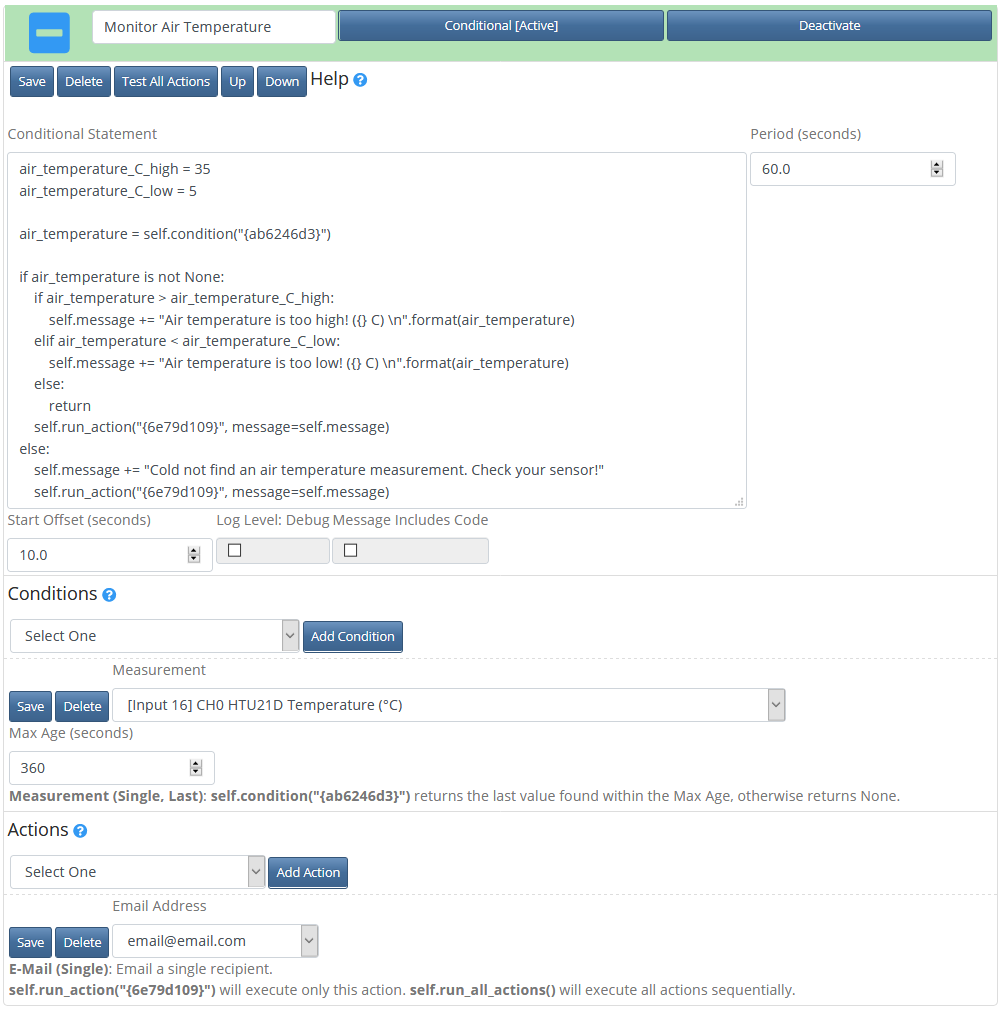
Email Notification for Water Level
Add a “Controller: Conditional” function. Add the Condition “Measurement (Single, Last), and set it to the GPIO State Input measurement. Add the Action “E-Mail (Single)” and set it to the email address you will want to be notified. Copy the following code to the Conditional Statement, then replace “asdf1234” with the ID associated with your Measurement Condition, and “qwer5678” with the ID associated with your Email Action.
bool_water_float = self.condition("{asdf1234}")

if bool_water_float is not None:
    if bool_water_float == 1:
        self.message += "The water level is low. Add water.\n"
        self.run_action("{qwer5678}", message=self.message)
else:
    self.message += "No water float measurement found!"
    self.run_action("{qwer5678}", message=self.message)
This code is configured to send an email notification that the water level is low when the float sensor GPIO is pulled to 3.3-volts (high). If, however, your float sensor circuit pulls the GPIO pin low (0 volts) when the water level is low, change line 4 from this: if bool_water_float == 1:
to this: if bool_water_float == 0:
Exhaust Timer
Add a “Trigger: Timer (Duration)” function, then add the Action “Output (Duration)” and set it to the exhaust output and the State to “on” and the Duration to “60” seconds, then save the Action. Set the function Period to “3600”, save, then activate. This will turn the exhaust fan on for 60 seconds every 3600 seconds (1 hour).
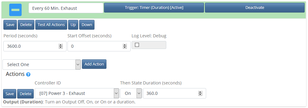
DSLR Camera Timelapse
The following configures a DSLR camera to acquire photos at a regular interval using a secondary neutral light described previously in this publication. This configuration also makes use of two additional outputs that control a remote shutter cable connected to the camera by activating one output to actuate the focus (DSLR Focus) and another output to activate the shutter (DSLR Shutter). You may need to adjust your configuration to suit your needs if your system operates differently than this.
Add a “Controller: Conditional” function and set Period (Seconds) to 7200 to capture photos every 2 hours (or any other desired period). Add the Action “Output (Duration)” and set Controller ID to the “Photo Light On Only” output and the State to “on”. Add the Action “Output (Duration)” and set Controller ID to the “Photo Light On Only” output and the State to “off”. Add the Action “Output (Duration)” and set Controller ID to the “DSLR Focus” output and the State to “on”. Add the Action “Output (Duration)” and set Controller ID to the “DSLR Focus” output and the State to “off”. Add the Action “Output (Duration)” and set Controller ID to the “DSLR Shutter” output and the State to “on”. Add the Action “Output (Duration)” and set Controller ID to the “DSLR Shutter” output and the State to “off”. Copy the following code to the Conditional Statement, then replace “PHOTO_LIGHT_ON_ONLY_ON_ID” with the ID associated with the Condition turning Photo Light On Only on, “PHOTO_LIGHT_ON_ONLY_OFF_ID” with the ID associated with the Condition turning Photo Light On Only off, “DSLR_FOCUS_ON_ID” with the ID associated with the Condition turning DSLR Focus on, “DSLR_FOCUS_OFF_ID” with the ID associated with the Condition turning DSLR Focus off, “DSLR_SHUTTER_ON_ID” with the ID associated with the Condition turning DSLR Shutter on, and “DSLR_SHUTTER_OFF_ID” with the ID associated with the Condition turning DSLR Shutter off.
import time

self.run_action("{PHOTO_LIGHT_ON_ONLY_ON_ID}")  # Photo Light On Only (ON)
time.sleep(3)

self.run_action("{DSLR_FOCUS_ON_ID}")  # Stage 1 On
time.sleep(1)
self.run_action("{DSLR_SHUTTER_ON_ID}")  # Stage 2 On
time.sleep(1)
self.run_action("{DSLR_SHUTTER_OFF_ID}")  # Stage 2 Off
time.sleep(1)
self.run_action("{DSLR_FOCUS_OFF_ID}")  # Stage 1 Off

self.run_action("{PHOTO_LIGHT_ON_ONLY_OFF_ID}")  # Photo Light On Only (OFF)
This will turn only the Photo Light on during the photo capture. For a more detailed description of how this works, see the previous two sections discussing Lighting and Outputs.
Adding and Configuring the LCD
On the Setup -> Function page, add a “20×4 Generic LCD” (or “16×2 Generic LCD” if using a 16 character, 2 line LCD). Set the Address (I2C) to the address of your LCD and the Period to how often you want the LCD to update or display the next set of lines. For configuring what is displayed on the LCD, there are display sets. By default, there is one display set, which is a set of data you can set to be displayed on the lines of the LCD. If you would like to display more data, you can change “Number of Line Sets” from 1 to your desired number of line sets to be displayed. You can create as many display sets as desired. The Period will determine how often the display cycles between these display sets. Activate the LCD and verify the LCD starts displaying data.
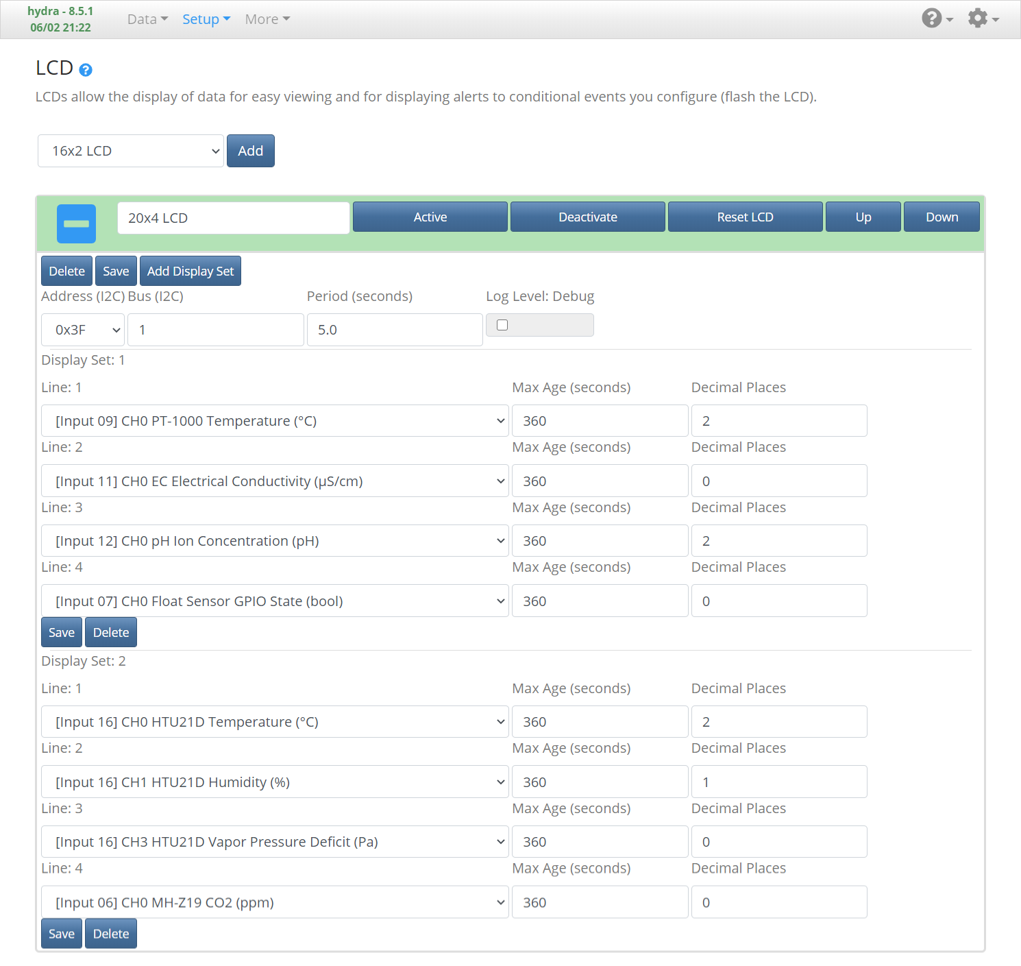
Adding and Configuring the Camera
If using a Raspberry Pi camera, ensure it’s properly connected and it has been enabled through the menu accessible with the command sudo raspi-config or from the Configure -> Raspberry Pi menu. Make sure you reboot after enabling the camera for your changes to take effect.
Navigate to the More -> Camera page, select the “PiCamera” Library (or “opencv” or “fswebcam” if using a USB camera), then click Add. Click “Capture Still” to see if an image can be acquired from the camera. There are a number of options that can be configured, including Output, which is the output to be turned on prior to acquiring an image. This is useful for taking photos at night by turning on a light while the photo is being acquired. See the previous Lighting and Output sections for descriptions of a custom lighting configuration that enables activating a photo light if you desire more neutral lighting during photos than your grow light can provide. The setting Duration (Output) is the number of seconds to turn the output on prior to taking the photo, which is useful if your lights take several seconds to turn on or warm up (such as with fluorescent bulbs). There are also options for setting the still image and live streaming resolutions. It’s advised to first test with the default settings, as certain settings combinations may prevent images from being acquired properly.
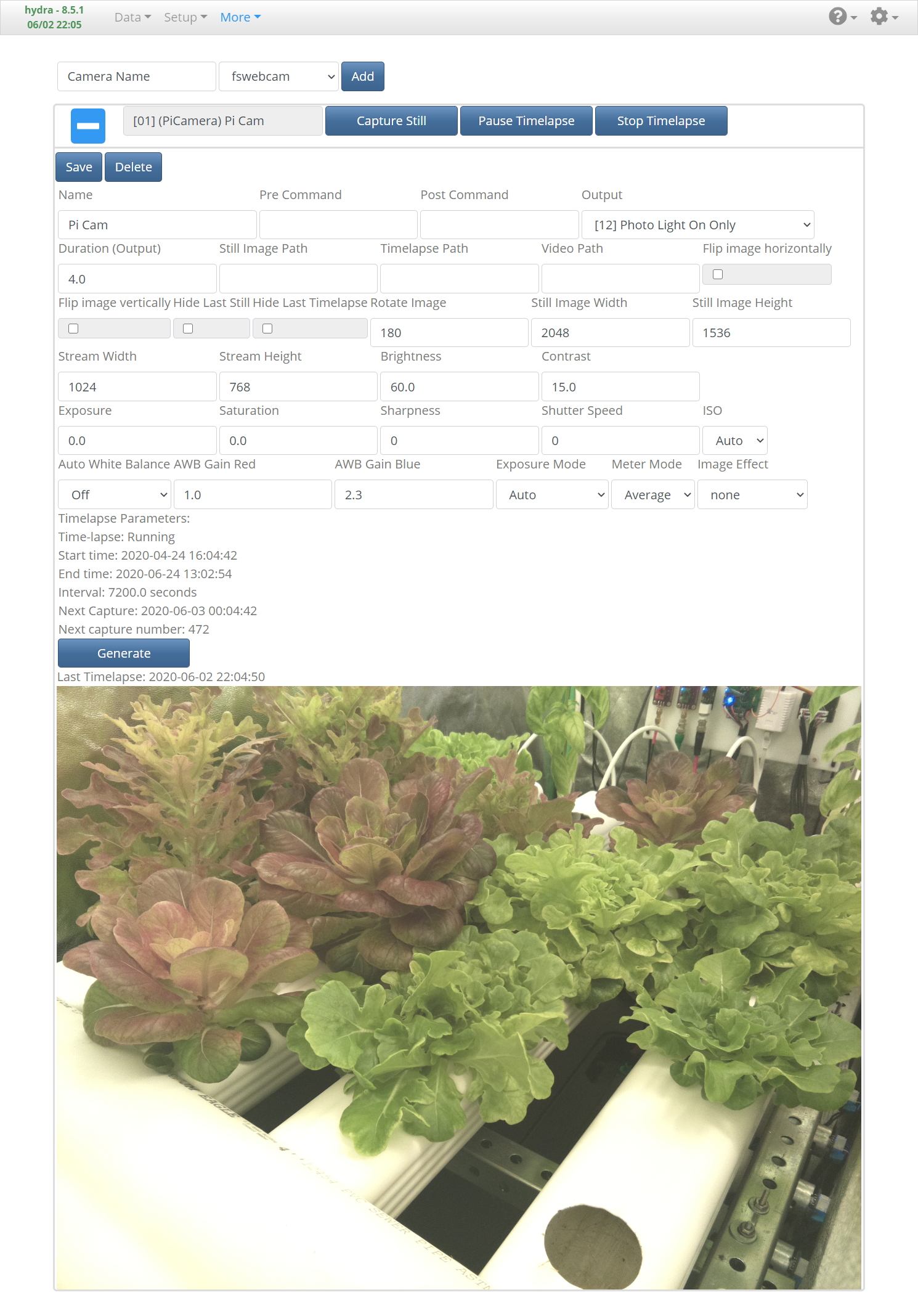
Adding and Configuring a Dashboard
On the Data -> Dashboard page, there are many types of widgets that can be added, organized by dragging, and resized. Perhaps the most useful widget is the Graph. Graphs allow you to select any number of Inputs, Outputs, PID controllers, and other measurements to be displayed on a historical graph. Graphs are updated automatically with new data, so you always see the latest measurements. There are also a number of settings to tune the graph to your liking, including the x-axis duration, series colors, and range selector, among others. You can also create multiple dashboards to organize different views, or to prevent one dashboard from becoming too cluttered. I won’t go into too much detail here, but suffice to say, configuring a dashboard and exploring the various widgets is one of the more fun experiences in Mycodo.
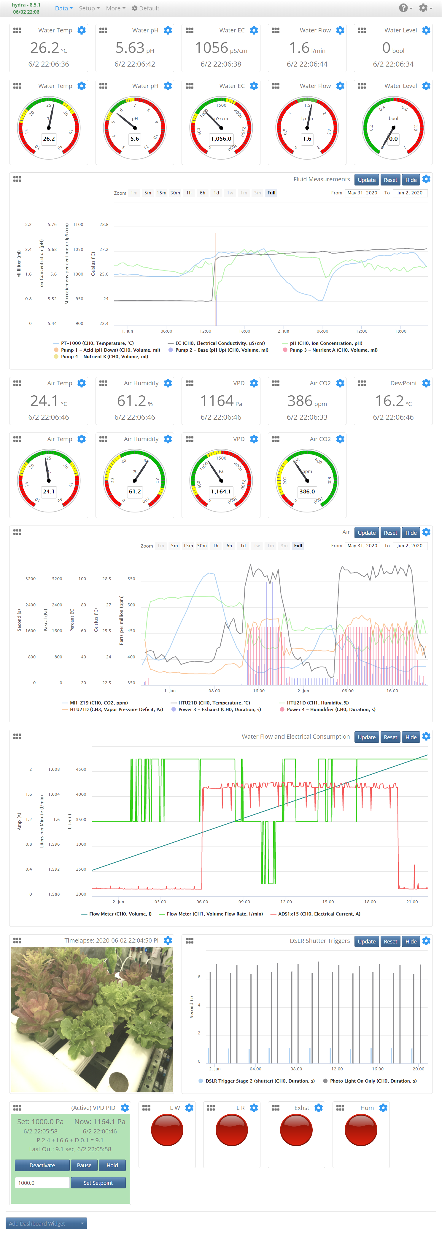
Automation Epilogue
Now that automation has been set up and is running, you’ll want to run your system for at least a few days before entrusting it to care for your plants. This will give you a chance to find potential issues and correct them. You’ll want to ensure the system can properly adjust nutrients and pH. You can test this by removing water from the reservoir and replacing it with fresh water, which should raise the pH and lower the electrical conductivity. You should also ensure lighting, exhaust, and other functions are operating as expected.
Plant Cultivation
Once Mycodo has been configured and monitored for a sufficient amount of time to determine it’s operating as expected, it’s safe to begin growing plants.
Biocontrol
With the system operational, it’s only a matter of when, not if, undesirable microorganisms will find the large amount of nutrient-rich water and begin to feast, potentially causing plant disease and crop loss. It’s far easier to initially establish desirable microorganisms in the system at the beginning to competitively-exclude undesirable microbes, than to try to exclude undesirable microbes later if they’ve been allowed established themselves. Therefore, I recommend inoculating a new water system with a healthy community of microorganisms.
There is debate about the best method for doing this, but what’s worked for me is introducing a small soil sample as well as a commercial biocontrol agent. The soil will introduce a large number of soil-associated microorganisms and the biocontrol agent will inoculate the system with a known beneficial microorganism known to combats pathogens. To inoculate with soil, I placed 20 g of potting soil in a small mesh bag and steeped it in the water reservoir for 30 minutes. For the biocontrol agent, I chose to use the bacterium Streptomyces griseoviridis, which has been observed to combat pathogens and increase yields. This bacterium is sold under the commercial name
It should be noted that deep-cleaning to remove potential contaminants is not advised (unless you had a particularly bad contamination occur), as this could negatively impact the established S. griseoviridis and other beneficial microbes. Rather, it is recommended not to use any chemical or mechanical cleaning methods following inoculation of biocontrol agents. This is the beauty of biocontrol. Rather than decontaminating undesired microorganisms following an infection, we’ve purposefully established a beneficial community that will compete with any pathogens trying to establish themselves. Although this is will not be able to combat every pathogen, as long as we support the health of our beneficial microorganisms, we’ve conferred reasonable protection to our system. You should still monitor the health of your plants and respond quickly to any decreases in health or yields by assessing the underlying cause and developing actions to mitigate the issue.
Planting Seeds
Before planting, you should consider the quantity and rate you would like to harvest. If you plant to the maximum capacity of your system, you will harvest a large amount at once, with long periods between harvests. However, if you stagger your planting, your harvests will be staggered as well, with smaller harvests at a more frequent rate. Below is one example schedule for growing lettuce in a system using 6 channels with 10 planting holes per channel, that will continually yield a 10-plant harvest every week, starting at the 8th week. Note that every week 10 seeds are planted, however you might consider planting 11 or 12 seeds to ensure you have enough to fill the entire channel should some seedlings not perform well.
| Week | Actions |
|---|---|
| 1 | Start 10 seeds germinating (set A) |
| 2 | Continue growing seeds in nursery tray (set A). Start 10 seeds germinating (set B). |
| 3 | Plant 10 seedlings (set A) in channel 1. Continue growing seeds in nursery tray (set B). Start 10 seeds germinating (set C). |
| 4 | Plant 10 seedlings (set B) in channel 2. Continue growing seeds in nursery tray (set C). Start 10 seeds germinating (set D). |
| 5 | Plant 10 seedlings (set C) in channel 3. Continue growing seeds in nursery tray (set D). Start 10 seeds germinating (set E). |
| 6 | Plant 10 seedlings (set D) in channel 4. Continue growing seeds in nursery tray (set E). Start 10 seeds germinating (set F). |
| 7 | Plant 10 seedlings (set E) in channel 5. Continue growing seeds in nursery tray (set F). Start 10 seeds germinating (set G). |
| 8 | Harvest plants from channel 1. Plant 10 seedlings (set F) in channel 6. Continue growing seeds in nursery tray (set G). Start 10 seeds germinating (set H). |
| 9 | Harvest plants from channel 2. Plant 10 seedlings (set G) in channel 1. Continue growing seeds in nursery tray (set H). Start 10 seeds germinating (set I). |
| … | Continue this cycle and you will have a harvest of 10 mature lettuce plants every week. |
For hydroponic systems, seeds are planted in supporting substrates rather than nutritive substrates like soil. These are typically in the form of small cubes with a hole in the center to plant a seed. Place one or two seeds in each cube’s hole, then place your substrates in a germination tray. Hydrate the cubes with pure water. Don’t use the water from the hydroponic system, as the fertilizer concentration will likely be too high and germination may be disrupted or the seedling may become injured or have its growth stunted. If there’s a significant amount of excess water that drained from the cubes while hydrating them, pour it out from the tray to reduce the risk of microbial growth. Leave only the water in the cubes and a small amount on the bottom of the tray. Place a lid on the tray to retain humidify and place the tray in a warm area or on top of a heating mat. Check periodically that the cubes are still moist and add water as needed.
It will generally take a few days to a week for your plants to germinate, depending on the seed. Once the seeds have germinated, start watering them with a dilute nutrient solution, roughly 1/4 to 1/2 the concentration of your hydroponic system (300 – 500 μS/cm), and expose them to light. Grow the seedlings in the nursery tray for a week or two until the first sets of true leaves form. This acclimates the plants to handle the more intense growing conditions of the hydroponic system. Make sure you supply your seedlings with ample light to prevent excessive etiolation (Josse and Halliday 2008). If long, weak stem growth is observed, increase the light intensity. You can also slowly increase the nutrient concentration to acclimate them to a higher concentration prior to transferring to the hydroponic system. Once the seedlings are about 2 to 3 inches tall, break apart the individual cubes and place one cube in each hole of the hydroponic channels.
Planted in this tutorial were the Salanova Premier Collection pelleted lettuce seeds (red oakleaf, red butter, green oakleaf, and green butter lettuces) and Genovese pelleted basil seeds.
Maturation
Over the next few weeks, as your plants mature, you may need to adjust nutrient concentration, light intensity, air/water temperature, vapor pressure deficit, or other parameters. Pay attention to the health of your plants and respond to any irregularities by researching and investigating the symptoms you observe to develop an understanding of the potential causes and to develop corrective measures. It may take several attempts before you develop the skill and knowledge to consistently yield bountiful harvests.
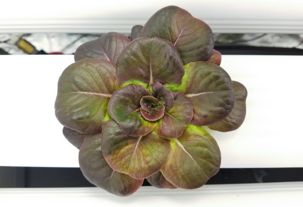
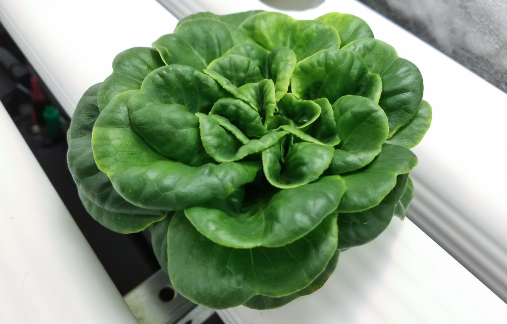
For these lettuce varieties, be cautious of using too much light or too high of a nutrient concentration, as this can cause your plants to grow too fast, resulting in dense center leaf crowding, curled leaf tips, and tip burn. Expect that some degree of tuning will be required to develop a configuration for optimal plant growth in your particular system. I recommend searching the scientific literature for optimal parameters for your particular crop in order to develop a good base from which to begin tuning. There is already ample literature on hydroponic lettuce cultivation and optimal parameters for nutrients (Gent 2003; Cometti et al. 2013), temperature (Thompson et al. 1998; Gent 2016), and light (Korkmaz et al. 1999; Gent 2014; Zhang et al. 2018), among others.
Harvest
The lettuces grown in this article will typically be ready to harvest in approximately 4 to 6 weeks after planting, depending on the light intensity, nutrient concentration, and temperature. To harvest, simply pull the plant out of the growth channel. These lettuces are highly perishable, so it’s advised to harvest as close to the time you’re going to use them. If storing for later use, place them in a refrigerator at or below 40 °F. These varieties of lettuce are convenient to prepare because they can be broken into individual leaves by removing the base of the stem from the bottom, either by twisting with your hand or cutting with a small knife.
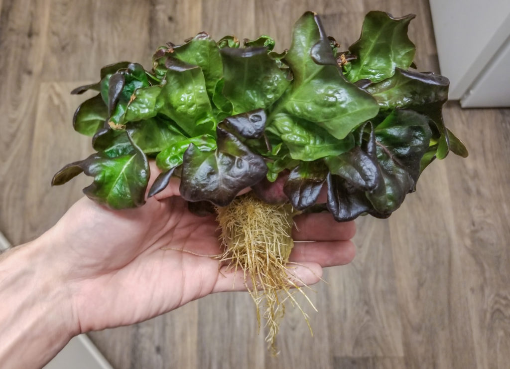
Future Directions
There’s a lot of possible modifications that can be made to improve or expand this system. Here are just a few that came to mind:
- Add a
dissolved oxygen sensor to monitor the water dissolved oxygen (DO) concentration or couple it with an air pump and air stone to regulate the amount of DO in the water system. - Add an
oxidation-reduction potential sensor to monitor the water oxidation-reduction potential (ORP) or couple it with peristaltic pumps and solutions to regulate ORP. - Add ducting to the lighting fixtures to reduce heat buildup in the grow tent by exhausting it outside the tent.
- Add a solenoid valve to automatically open the flow of a fresh water source to the reservoir when the level gets low.
- Add an air or water heater to maintain an optimal temperature in cold environments.
- Add a dehumidifier or additional exhaust mechanisms to regulate vapor pressure deficit in high humidity environments.
- Add a thermal pad with a temperature sensor to regulate a consistent temperature for germinating trays of seeds in a nursery area prior to planting in the channels.
Log In to View My System
My system was open to guest logins for the first month after this article’s release, and has now been disabled while I work on my next project. Check back soon for my next article.
References
- Barbosa GL, Gadelha FDA, Kublik N, Proctor A, Reichelm L, Weissinger E, Wohlleb GM, Halden RU. 2015. Comparison of Land, Water, and Energy Requirements of Lettuce Grown Using Hydroponic vs. Conventional Agricultural Methods. International Journal of Environmental Research and Public Health 12:6879–6891. DOI 10.3390/ijerph120606879
- Cometti NN, Bremenkamp DM, Galon K, Hell LR, Zanotelli MF. 2013. Cooling and concentration of nutrient solution in hydroponic lettuce crop. Horticultura Brasileira 31:287–292. DOI 10.1590/S0102-05362013000200018
- Gent MP. 2012. Composition of hydroponic lettuce: effect of time of day, plant size, and season. Journal of the Science of Food and Agriculture 92:542–550. DOI 10.1002/jsfa.4604
- Gent MPN. 2014. Effect of Daily Light Integral on Composition of Hydroponic Lettuce. HortScience 49:173–179. DOI 10.21273/HORTSCI.49.2.173
- Gent MPN. 2016. Effect of temperature on composition of hydroponic lettuce. Acta Hortic 95–100. DOI 10.17660/ActaHortic.2016.1123.13
- Gent MPN. 2003. Solution Electrical Conductivity and Ratio of Nitrate to Other Nutrients Affect Accumulation of Nitrate in Hydroponic Lettuce. HortScience 38:222–227. DOI 10.21273/HORTSCI.38.2.222
- Josse E-M, Halliday KJ. 2008. Skotomorphogenesis: The Dark Side of Light Signalling. Current Biology 18:R1144–R1146. DOI 10.1016/j.cub.2008.10.034
- Korkmaz A, Pill WG, Cobb BB. 1999. Rate and Synchrony of Seed Germination Influence Growth of Hydroponic Lettuce. HortScience 34:100–103. DOI 10.21273/HORTSCI.34.1.100
- Mycostop Research Results. Retrieved March 8, 2020. <http://www.agbio-inc.com/mycostop-research-results.html>
- Thompson HC, Langhans RW, Both A-J, Albright LD. 1998. Shoot and Root Temperature Effects on Lettuce Growth in a Floating Hydroponic System. Journal of the American Society for Horticultural Science 123:361–364. DOI 10.21273/JASHS.123.3.361
- Zhang X, He D, Niu G, Yan Z, Song J. 2018. Effects of environment lighting on the growth, photosynthesis, and quality of hydroponic lettuce in a plant factory. International Journal of Agricultural and Biological Engineering 11:33–40. DOI 10.25165/j.ijabe.20181102.3420
Latest Articles
- Mushroom Cultivation Automation: From Foraging to FruitingMushrooms are a unique and often mysterious organism. They’re not quite plants and not quite animals. As a fungus, mushrooms represent a distinct evolutionary lineage. Fungi grow as a single-cell yeast form (used in beer, wine, and bread making) and multi-cellular, thread-like mycelia that often produce fruiting bodies (mushrooms) and sclerotia (e.g. truffles), and are responsible for the decomposition of the vast majority of dead plant matter. Understanding life cycle of mushroom fungi is a valuable skill if you wish to harness this knowledge for mushroom cultivation.
- Automated Hydroponic System BuildHydroponic farming is a method of growing crops without soil, with the main benefits of environmental and nutrient control, water conservation, and reduction of labor. This technique relies on a number of technologies that the principles of automation can be applied in order to improve yield and consistency. In this article and accompanying video, I’ll show you how to built a hydroponic system with basic components and automate it using the open source software Mycodo running on a Raspberry Pi single board computer.
- Remote Radiation MonitoringRadiation is the transmission of energy through space in the form of a particle or wave. These can be generated by instruments or… Read more: Remote Radiation Monitoring
- LoRaWAN Tracker and MapperLoRaWAN is a great long-distance, low-power transmission protocol. One of the questions that often comes up after deploying a gateway and nodes is… Read more: LoRaWAN Tracker and Mapper
- Outdoor LoRaWAN GatewayI’ve been heavily involved with sensors and remote sensing for many years. Recently, I’ve become intrigued with remote sensing, and began my exploration… Read more: Outdoor LoRaWAN Gateway
- Bringing a Vintage Telegraph into the Digital AgeI recently inherited a key on board (KOB) telegraph that my late grandfather used to practice Morse code with when he was a… Read more: Bringing a Vintage Telegraph into the Digital Age
WOW !! I dream Come True,, Congratulations…..
I’m wanting to start on making one of these, but due to the cost of components I’m wondering if I can start with only one or two of the functions running to start, and add further sensors and functionality down the road? Does the software go all crazy if it’s not receiving input from all the specified sensors? I want to start with just ph sensor, and ph control via the dosing pump, probably add temperature too since I know that can be a factor in PH sensing accuracy.
The software is scalable so you can add as few or as many inputs, outputs, and functions as you desire. There’s no conflict from having too few devices.
dude thats impressive..so inspired
Awesome video and literature. If I add1 more peristaltic pump in the system do I have to code it in t Mycodo or does it automatically recognize it? How about the water fill and water dump solenoids? If I added that does it require coding or is it tunable in Mycodo?
All of what you described can be done through the web interface, no coding necessary. There are generic peristaltic pump and generic on/off outputs you can add and configure with a few clicks.
I had sent you a email asking about this and 1 more thing. If I want to run 2 reservoirs like in your video except that each reservoir is feeding 2 different trays at different EC. Will that require programming? Im super excited to build mine!
No more programming than is mentioned in this build article. For however many reservoirs/sensor arrays you have, just multiply the steps for setting up nutrient/pH regulation.
amazing job mate! congrats.
This is one of the best written and physically solid presentations of a high end DIY build. I am looking forward to making this as my next major project. Thank you for doing such a great job and I look forward to hearing more.
AWESOME presentation, truly. This is the best prototype system I have seen online.
Do you have any thoughts on aquaculture automation?
Any estimate on how automated (physical non-intervention) your solutions might become?
I don’t have much experience with automating aquaculture (which I hope to change soon), but I don’t think the principles would be much different than this.
Could you clarify your second question? So far, I’ve only had to replenish water in the reservoir, since I didn’t have a water source near to connect to a solenoid valve. So, there’s very little intervention needed as it stands.
I need a system like this with proposed modification. I have 15fish nursery each producing 1000 litres of nutrient rich “waste” water. I need to convert this water into resource for fruit n vegetable farming. Kindly let me know possible cost implication. The Hydro Victoria Fish Farm also runs a RAS system(1200liters under circulation in a 20m by 15m godown roofed with ironsheets n walled by 60% greenhouse paper for catfish n tilapia egg propagation (hatching n nursing).The farm is located along the shores of Lake Victoria in Busia County, at Port Victoria town in Kenya (Africa).
Looks like a fantastic setup. Great write-up too. Thanks for sharing it!
One thing that is missing IMHO is an itemised price indication for the BOM. This could help prospective builders decide whether they want to pursue such an endeavour.
A lot of items are quite pricey (eg: Atlas Scientific). What is your estimated total cost for the automation and sensing side of this project?
Prices sometimes change and the Amazon Associate terms prohibit listing of prices (because they change), but the total for everything except the tools should be around $1200. You can save a few hundred $ by using generic peristaltic pumps and run them for short durations of time. You could also use less expensive water sensors, but non-lab-grade probes can’t handle being submerged indefinitely like the ones produced by Atlas Scientific, so YMMV.
If this were to be done in a classroom for an educational display (with the bonus of green production), would the tent be required? From my understanding after reading your post and some research, the tent helps to maintain humidity, temperature and reflect light for maximum efficiency of LED’s. If a plexiglass front wall barrier was constructed within a sealed “box” would the LED’s need to be on longer or would an additional panel need to be added to account for the lost light? New to aquaponics, have gardened before and have been teaching some courses on robotics and automation lately. This seems like the perfect project to help tie everything together!
I use the tent primarily for light retention and to be able to have more control over the environment. If using grow lights, the tent is really useful, as the lights are fairly intense and you wouldn’t want prolonged exposure to them. For education, I would recommend building this against a window that gets a good amount of sunlight, with a slightly different configuration that has channels stacked above one another, where one channel’s outflow goes into the next channel, with the last channel returning the water to the reservoir. This open design lets you see everything that’s happening. I believe this type of design is called a greenwall, or is at least very similar to one.
I work within the interior of the building, with no windows, only skylights. I would be looking to partner this idea with a green wall using vertical tubes, a reflective material on the backing wall, and the LED grow lights positioned facing the wall (and plants). I have seen consumer products set up within the classroom and the reflected light doesn’t seem to be as harsh when the LED’s are not directly above or eye level. The automation aspect of this project is what really caught my attention. Thanks for the quick reply and sharing such an amazing project.
Checking out your content, you should really learn how to use the mirror tool in fusion 360. I keep feeling so bad for you watching you recreate profiles!
You can also use the project function to make the geometry much faster.
I’m familiar with mirror, I just chose not to use it here. I also did use project for some of the construction. They’re simple parts, there’s no harm in taking my time so the time-lapses come out longer than 2 seconds. The goal was to make an entertaining video, not design the parts with the minimal number of actions. Thanks for the tips!
This looks awesome, anywhere to buy the smart system? I have a basic setup and like to start automation. It would be great to start with your hardware and build top of it. :) Thanks.
There is not. I provide the software and general guidance. Some assembly is required.
Awesome project. I just saw all the Mycodo work. Amazing! I will certainly try it out the automation work in my aeroponic system. thanks also for open-sourcing this.
Fantastic work and effort to put this together, job very well done. I’ve seen some smart hydro systems before, but never one fully automated with nutrient & acid pumps. Also thanks for making me aware of Mycodo, looks super useful and have a few ideas for use.
Out of curiosity, why go with a NFT system? And why no netpots?
Thank you. I chose NFT because I had some familiarity with it and because of its simplicity. With netpots, you need extra materials (pots) and a longer seedling growth period (for longer roots) before introduction into the system.
Have you looked at other studies on other beneficial bacteria other than Mycostop?
What did not make the cut and may be a waste of money?
Popular ones are Hydroguard, Liquid Ocra, Great White, UC Roots, BooBloom
Opinions also on roots stimulators / enzymes?
You’ve noted controls for a humidifier, but there didn’t appear to be anything to generate humidity in the Materials and Parts list. What did you use for this?
Any consumer humidifier should be fine. I ended up using an ultrasonic humidifier transducer with a float to keep the proper water level over the transducer. This was set inside a 2 gallon jug with the lid cut off, with a laundry detergent cup cut and placed over the top of the transducer to prevent water from splashing out of the container. I didn’t record this being built, but I may modify the article with a build section and add to the parts list. I’ll try to remember to reply to this thread when I do.
Hi Kyle, Great project, I think I will be making one similar using your guides. I plan to have a mix of 5V and 3.3V devices using I2C. I am confused about your section “Connecting the Sensors,…” and especially the Note 1 about level shifting. You mention all your devices are 3.3-5V compatible, so it seems like you are using 3.3V to run SDA and SCL back to the pi, and would also be using 3.3V to power your devices. However in all of your schematics you have the power for these devices connected to the 5V pin on the RPi. Is this a mistake in the diagrams or am I missing something? I am thinking of using a level shifter and powering my 5V devices with a separate voltage source (or the pi 5V pin 2/4) and all the 3.3V devices from the pi 3.3V pin 1.
It’s not an error, the schematics are how I actually wired it. The only circumstance where using 5 volts on the I2C lines of the Pi is acceptable is if you don’t have the SDA or SCL lines pulled to 5 volts. In reviewing my schematic, my LCD requires 5 volts, but the rest of my I2C devices can operate on either 3.3 or 5 volts. My LCD doesn’t pull the I2C lines to the input voltage, it only pulls them low for communication. I didn’t have a level shifter available when wiring, so it’s what I went with. I should really go back and add one for the LCD and move the other devices to the 3.3 volt line in the schematic, or add a note explaining this anomaly in the schematics.
See:
1: https://www.raspberrypi.org/forums/viewtopic.php?p=924630&sid=a312daa2503b9ff3f7a9c388ab1cbc24#p924630
2: https://raspberrypi.stackexchange.com/a/68200
Edit: I just updated the build documentation to include “Note 2” explaining the anomaly.
Yow this is fantastic. I might build & install this winter.
Question, how easy can we add a “nutrients schedule”?
From clone to grow room, we all start with a low EC and increase up to a “max” value that is considered safe for ~90% of the strains. Worst case if there’s some burning, hopefully you were around to notice and lower. When switch nutrients from grow to bloom, we can again start to increase the EC level. Also consider some growing method requires ~7 days flushing w/ clean water to “clean” the fruits.
Quickly I couldn’t tell if such schedule was possible.
Switching from grow to bloom and then to “flush” mode is often a decision taken by the operator. Does Mycodo support such a thing? Quickly I’d say … maybe something like a down box that allows operator to chose the profile/mode the system is running? Ex. : Clone, Vegetable/grow, Flower/bloom, Flush. The scroll down menu would support “create new profile” with different settings and be able to save it. Someone then create the following profiles :
Clone-Week1
Clone-Week2
…
Grow-Week1
…
Grow-Weekn
Bloom-Week1
…
Bloom-Weekn
Flush
But once switching from grow to bloom, the system should be able to automatically knows it juste entered Bloom-Week1 – keep note of this info somewhere. When it reaches Week2, the application should automatically switch to week2 w/o the need of the operator.
Also… when switching from grow to bloom nutrients, someone needs to empty the A & B pumps’ tubes from the liquid currently in place. I would run this system w/ to 2 more pumps.
Hi I would really love to build this and support you at the same time by purchasing items from your list the problem is that I do not have enough experience and your video goes way to fast for me as I have no experience. If you could make a video showing where you are plugging each wire Or have more close ups images of the wiring and bread boards so a novice can understand and build.
Thanks
Seann
What I produce is not meant for someone with no experience (although that shouldn’t discourage anyone from trying). There are a lot of other resources to learn about hardware and software for a beginner. Best of luck.
Hi Kyle, very great project. Its going to help me for my secondary school project. One thing is that the peralistic pumps are expensive can you tell me how to use normal peralistic pumps(I mean by the ones that are controlled by positive and negative wiring only) in the project. Thank you
Claude,
Generic Peristaltic pumps could always be used with Mycodo. You would simply wire the pump to its power supply with a relay in-line with the positive wire. Then, in Mycodo you would create an On/Off GPIO Output and set it to the pin connected to control the relay. This allows the pump to be turned on for durations of time. Additionally, since the release of this article, I’ve created a Generic Peristaltic Pump Output module in Mycodo, which allows for outputting specific volumes in addition to durations of time (following the measurement of your particular pump’s flow rate in ml/min and setting this value in the output options).
thanks a lot Kyle ,1) can you please send me a small simple schematic so i could understand it more pls.
2)also the Ethernet cable wiring in the power box is mentioned to connect:
One Ethernet wire to the ground (-) input of each relay module.
One Ethernet wire to the positive (+) input of each relay module.
One Ethernet wire to the channel 1 signal input of the mechanical relay.
One Ethernet wire to the channel 2 signal input of the mechanical relay.
One Ethernet wire to the channel 1 signal input of the solid state relay.
One Ethernet wire to the channel 2 signal input of the solid state relay.
is there specific wires of the Ethernet cable that i need to connect or any cable is acceptable??
3) and can apply the atlas scientific wifi hydroponics kit instead of the individual kits?? (it can connect raspberry pi via 4 way pbt connector that has scl,sda,grd,vcc)
1. Sorry I am not able to generate schematics by request.
2. The color of wire does not matter, so long as each end is connected to the proper place.
3. I’m not familiar with the kit you reference.
Did you have to change the water or add water regularly?
That depends on how many plants, the plant species, the air humidity, the temperature, whether there has been a contamination, among other factors. Water will be removed from the system, either by plants or evaporation, and need to be replenished. Certain nutrients may build up and require refreshing the reservoir. Water can be set to automatically be refilled with a water level sensor and solenoid connected to a secondary water source.
Great video and instructions. I just set mine up with only ph so far and I love it. Wondering if you were planning on adding any additional logging parse ability or a way to upload it into powerbi or a like program. I’m interested in the trends over time for my stats (once I have all the other probes) and the ability to review historical data without loading the pi up. Something that could like upload/dump logs to a cloud source would be cool. Otherwise this project is as perfect as could be. Im looking forward to the ORP add on as well.
There exists the ability to create your own Input, Output, and Function modules, so exporting data can be accomplished any way you see fit. I’ve created several modules myself for personal projects to transfer data over LoRaWAN, The Things Network, public radiation monitoring maps, TTN Mapper-Tracker, and others.
Awesome! Looking forward to giving it a try!
You did an incredible job. I am in the process of carrying out the same project. To facilitate the wiring I use the “Whitebox Labs Tentacle T3”.
I just found a small error, the default address of the atlas pump is 103 (0x67), it’s EC which is 100. So I changed the address of the wrong module.
Keep up this great job. If you could add the CO2 Atlas that would be cool.
the probes that i have chose are all analog signaled can i attach an analog to digital converter so i could connected them to scl and sda
Your answer can be found in the manual: https://kizniche.github.io/Mycodo/Analog-To-Digital-Converters/
Hi, fantastic job. I have arduino project on the way but coding is not easy . Would like to test yot system. Plese teel me one thig: I have here a Raspberry Pi model B+ with 512Mb. What is your opinion, will it be enough, even without camera or wifi? or Model3 is really necessary? I wish i could find a use for the model 1 i have here :) Thank you, and congrats
The version 1 Pi will likely work, but will lack performance compared to v2, 3, and 4. The last v1 I ran Mycodo on was in 2015, and that was a much different piece of software than it is today. That Pi now sits in my history museum, aka project graveyard.
Thank you for quick answer. I live in front of a graveyard :) but still hope to use the RPI before sending to the other side of the street:) For now is working as an internet radio and works reasonably … I have ordered a RPi3 to work with your program since i´ve an hydroponic system and i’m sure i´ll learn a lot. Stay safe :)
How many fans and other equipment did you use and for what purposes? Sorry I was having trouble understanding the temperature and humidity regulation part
There is one fan and it’s used to lower both temperature and humidity if either rise above a certain threshold. More precisely, a simple conditional modulates the fan to regulate temperature and a PID controller modulates the fan to regulate vapor pressure deficit, which is based on both temperature and humidity.
Please disregard my first reply, what I meant was what if the temp and humidity decreased at a certain threshold, does your system have a way to increase these?
Not included in the build log is the addition of a humidifier. You could also add a heater. Any condition can be modulated for which there is both a sensor that an measure it and an electrical device or devices that can affect it.
Hey, Crazy read, one of the best automation experiments out there. I love doing these experiments as well. One suggestion for an add in feature can be a ppfd/par sensor, connected to an inexpensive hydraulic system/motorized system, that can lower and rise the light according to the ppfd required each cycle of the plant. As for when the plants grows in size, you can add an infrared sensor connected/glued to the ppfd sensor which can be lowered and raised to be always above the plant. I love over engineering stuff, automation is the way to go. The only thing left is a robotic butler to cook my meals.
instead of raising and lowering it might be better to dim and undim. less moving parts.
dim and undim would also work better in situation where you have multiple shelfs of a rack in a vertical situation.
as the plants grow taller.. you can dim.
or if you need it to be brighter you can turn on an additional lamp.
the camera feed can go to a simple cognitive vision module running on the PI
which calculates the distance of the light from the plant height.
when the plants are ready to move from veg to flowering, the robot can move the plant to the other grow tent.
sorry youll still have to cook for yourself :)
Had my light been designed to dim, I would have. I do know of others who have used Mycodo with methods to simulate sunrise and sunset as well as adjusting light output based on photon measurements at canopy of the growing plants.
I am really impressed. I have been thinking about hydroponics for the last few months , and this project is exactly what I need. I am seriously considering support via patreon. However, I have a question, will this work in regions with AC of 220~240 volts. The “Iot Relay – Enclosed High-power Power Relay for Raspberry Pi” does not support the mentioned voltage. Any thoughts about that. Thanks
Ali, there are many relays available to choose from. You’ll have to select an appropriate relay based on the control and switched voltages as well as the anticipated load. There are a lot of pre-built relay modules that should also be appropriate, as you are using a common AC voltage.
Will this work with other probes? I already have a ph and ec probe and ec/ph transmitter.
Maybe. There are only a few that are currently supported, but users can create their own custom Input modules. If you can provide a product link, I’ll check it out and let you know if I think it can be easily integrated into Mycodo.
I am working on my reef tank automation project. It’s very similar with your project. I had built cabinet, glue glass, setup the PVC pipe, pH and temperature sensor box, power control and meter box. I am going to build a dosing pump, auto water change (Remove salt water, and using EC to determine add fresh water or salt water), even Alkalinity meter by myself.
If you come to Taipei, welcome to my house to see my DIY projects.
Excellent! Thank you.
Do you have a video on how you built Mycodo? Or know of any resources that would tech you how to build something similar to it? I think that would be very interesting to watch for those wanting to create their own web based UI.
I don’t, but combining Flask and Bootstrap isn’t terribly difficult. I’ve had a lot of fun learning and building Mycodo’s UI using these,and there’s a lot of documentation out there on both.
you’re a beast!.. one of the best diy, congrats and thank you for the open source.. starting to build one.
Hello and great job! I am starting to purchase all of the components for this project. Do you know of any less expensive EC probes that would work?
Thank you. Unfortunately, quality EC sensors are rare. If you happen to find one start a topic on the forum and we can discuss it. kylegabriel.com/forum
Hello Kyle, great job, the pH and conductivity sensor can be submerged all the time? and the other query if the tank is of greater capacity does not affect that you have a smaller sample from the total values for example in a 2000 liter tank?
The water sensor probes are lab grade and can be submerged indefinitely. The sample size for measuring water parameters can remain the same, as this is simply a subsamples of the entire volume to determine if the chemicals have adequately mixed. The subsample serves to separate the sensors from the main reservoir, which is more susceptible to concentration gradients. The sampling chamber draws a water sample from the same line that discharges into the channels, after the pump, which is located on the opposite side of the reservoir where chemicals are added.
What a great job!
I’ve got lots of information and help from your article, and thanks a lot for your hard work.
How long did it take for you to finish the project?
I worked on this for several months. I conceived it in December, began working on it in January, and was finished with everything (building, demo grows, filming, production, article) by June.
Hi Kyle,
for the grow light, I’m not quite sure why you referenced us to 1000W grow light Led for a 4×2′ grow tent? I see you used a 300W led initially. And correct me if I am wong, we should go for 32W per foot meter square, right? and if that is the case, then we are only growing our plant on 24”x23” , which should be a 2×2′. So, 4 multiply by 32W should give us 128W led needed. Can you please share with me your reference for choosing your LED ?
thanks!
The inverse-square law states for a point light source, every doubling of distance reduces light intensity to 1/4. Intensity loss is inevitable, and I found my 300W light was insufficient to cover the entire grow space. Regardless, I mention that I would not be investing much time discussing lighting and this should be researched on your own to determine your specific lighting needs, therefore the light I included in the BOM was just a good light with decent output that happened to be the same price that I bought my 300W light for several years ago, so I thought it was a good deal.
Nice work….going to try this project. Thank you
nice.
the thing with the frame and using the Maker Pipe connectors i dont understand is… how do you get that slight angle.
i took a look at their website and it seems the only angle possible is 45 degrees.
i guess what i have to do is make a slightly higher hole on one side, use a T connector for the side pipes that will hold the inlet
then use another T connector slightly rotated downward with a pipe headed towards the drain outlet. ok i think i got it.
I think I can picture what you’re describing. This is how I would do it (although there are probably multiple methods): with 4 pipes vertical as legs, two will be designated as the inlet side and two as the outlet side. T adapters will connect a bar that spans across the inlet pipes and anither T and bar for the outlet pipes. With the Ts, these bars can be moved up and down the vertical pipes, allowing you to adjust the height and tightening the T to lock it in place.
Hi this is an awesome read. I am also looking at trying to develop an automated hydroponic system as a special project during these times where mobility and recreation is limited. As I am new to all these things, may I ask if it is possible to implement this project using Raspberry Pi 2 model B? What changes need to be done?
Mycodo runs on all Pi versions, though it will be a bit slower on a Pi 2.
Hi Kyle, Great work mate!!! Thanks.
I had a question. I’m from India here most of the kits and electronic circuits which you mentioned to connect with the Raspberry pie are not available. Is it possible to run the same process and integrate it with locally available circuitries and chips .
Thanks,
Yes. There are a number of sensors and devices with built-in support, but there is also the ability to import custom user-created Inputs, Outputs, and Functions to add support for previously-unsupported hardware a d add new functionality.
Hey Kyle, after forwarding my raspberrypi IP over port 443 I am getting SSL certificate error, basically “this connection is not private”. Any idea how to fix this?
I know I can circumvent and visit the site anyways, but would like for others to be able to access the site without having to do this workaround. I’ve also tried disabling the “force https” option in the general mycodo configuration page, then forwarding port 80 (http) instead of 443, but the IP is still automatically redirected to HTTPS… any pointers would be greatly appreciated. Thanks!
I might have forced HTTPS with Flask-SSLify and forgot to remove the option in the config to disable SSL. I’ll look into that. If you’re using a domain (such as a dynamic DNS service), you can always get a free SSL certificate from letsencrypt and overwrite the files in your SSL directory of Mycodo. I’ve done this for some of my Mycodo instances that I shared to the public and didn’t want to scare anyone.
That did the trick! For Dynamic DNS I wrote a bash script scheduled with crontab to keep a type A DNS zone record updated with the current public IP. For the SSL cert I used letsencrypt, and completed the manual DNS challenge, verifying control over the hosted zone by inserting the key into a TXT DNS record. Thanks Kyle.
Hi Kyle,
This is super cool! Many thanks for sharing. I want to build this on my own.
I think the hardware setup – I need to get extra help.
May I ask – How long did it took you to do the actual setup? – (excluding all github/programming part of the work).
Are you still running the system as is? or have you made further improvement?
Cheers
You could probably build and set it all up in a weekend. My system is exactly as I described it in the article.
Kyle
Awesome work and dedication. I have already started using your mycodo on my rpi4. Can you enhance your code to include inputs from UI to control instruments. I am looking for controlling lights in some circumstances from website.
Hello Kyle,
Love the project and the detail you have put into it.
Am I right in thinking that as you are measuring and adding the nutrients etc as required that are needed that you do not need to flush the system on a regular basis? Was there ever a need to flush the system?
Did you dilute the liquid solution which is in the 4 bottles or is that as purchased?
Kind regards
James
Hi, James. Yes, pH solutions and A/B nutrient solutions are only added when needed and they are undiluted in the bottles. Having such tight control of nutrient/pH solutions means there’s very little excess being used. I have rarely needed to flush the tank. It’s somewhat difficult to determine if any particular nutrient is becoming excessive in the system over time, so refreshing the reservoir every so often may be beneficial.
Hi Kyle! Great project! Is it possible to buy your system or maybe you can recommend some videos to learn the basics?
Sorry, I don’t sell any kits. Here’s a good introductory video on the Raspberry Pi and sensors: https://youtu.be/gnE4v-PcYKQ
Hi Kyle, this project is sick! Really inspirational!
I want to try to replicate what you did but I don’t want to buy ALL the parts at once mostly for economical reasons. I am starting by buying a peristaltic pump (besides the raspberry pi). Do you think mycodo would work even if I only have this one widget connected?
Also, do you think you could point me at the python code you are using in mycodo to control the peristaltic pump? I hoping I could try to re-use that in a stand-alone script I can write and run through the terminal only.
Best,
Nicola
PS. Really, best project I have seen on the web ever.
Nicola, yes, Mycodo can operate a single pump using one of the several built-in outputs for controlling pumps.
Hi Kyle,
great article!
I had see at Atlas website that they have the tentacle t3 for raspberry, is that work with Mycodo?
How many sensors we need at all?
Mycodo can talk with MQTT broker?
Looking forward your kindly reply.
Many thanks.
Leandro
The tentacle t3 merely connects all like connections and provides pins to easily connect to each sensor’s power, ground, and communication pins, so yes it will work with Mycodo.
Mycodo can publish (Output) and subscribe (Input) to MQTT topics.
thanks. just one small but dangerous? point. im looking at what you actually wired at 7:36 and it doesnt jive with your schematic at https://kylegabriel.com/projects/wp-content/uploads/sites/3/2020/01/Power-Control-Box-wiring-01.png in the schematic you have the incoming power from the IEC 320 Panel Mount Power Socket ( L ) denoted by the red lines and they generally wire up to the extreme left screw terminals of both relays. whereas power going from the relays leaves through the extreme right screw terminals. but in the video you use the middle screw terminal. you dont use the middle screw terminals in your schematic though. i am afraid to continue because of this discrepancy.
You’re correct. My schematic is inaccurate and the first wire should be connected to the center terminal. The second wire is correct and connected to the normally open terminal. I’ll update the figure.
Amazing setup! I’ve been working on this build for an ebb and flow hydroponic system for the last month and I’m almost done. I added an air pump, water heater and reverse osmosis water system to the build. Too much fun!!
I’ve been really surprised on how much time I’ve sunk into the reverse osmosis build and the issues I’ve run into there. I’ve found that automated RO water with a float valve that tops off the reservoir has a lot of TDS issues due to TDS creep. The RO system needs to work in large batches at once so that it has time to flush the high TDS water sitting in the membrane and continue to produce low TDS water. When it’s just topping off the reservoir with small amounts of water then it’s topping off with the high TDS water sitting in the RO membrane. Also made me wonder about home systems with a pressure tank. After the first clean fill they start topping the tank with higher TDS water. I just ordered an auto flush flow valve that will flush the RO membrane everytime it gets used and also flush it every hour. Hopefully that takes care of things. I have high TDS well water at 400 to 450 ppm. After RO it’s around 20.
Keep up the amazing work!! I’m following the Mushroom build on Patreon and will be doing that in the future as well.
I ran into that issue as well but through trial and error found the middle screw terminal worked.
Hello! First off, must say im really impressed with the build. It really got me interested in Hydroponics!
Im trying to follow the guide and setup Mycodo now, but i cant find the ezo-pmp when following the guide.
I have followed it up to List_addr but sometimes i get a list of numbers, but no pump showing, sometimes i get no list and just “Enter Command” again.
The pump are set to I2C and showing blue led. Am i missing something?
Thanks for answer!
Sincerly,
Hi, Robert. First, enable I2C with “sudo raspi-config”, then reboot. After changing the pump to I2C mode, connect 3.3 volts, ground, SDA, and SCL from the Pi to the Pump. Then run “sudo i2cdetect -y 1” to scan your I2C bus 1 for devices. You should see a device listed on the table of possible device addresses. You can then disconnect your pump and rerun the i2cdetect command and you should then see the address has disappeared.
Hey Kyle, thank you for documenting all of this! Would it be possible to use https://atlas-scientific.com/kits/wi-fi-hydroponics-kit/ instead of buying the individual probes?
Yes, but you would still be connecting the Pi to the board all of the sensors connect to anyway, so you’re merely adding another piece of equipment to hold/organize the EZO sensor boards. You could use the wifi kit to upload to the cloud, then use MQTT to then subscribe to the remote server receiving the measurements, but you’re then adding several more components that could fail (router, internet service provider, remote server, etc.). It’s far more reliable to directly connect your Pi to the sensors.
I don’t have much knowledge of EE or Coding, but I would really like to try this project out. This project is awesome! Thank you so much for the through explanations. Only issue is that the project isn’t quite budget friendly. I did the math and it seems like it will be more than $1000 with the sensors and the pumps costing more than half. Are there more budget friendly products out there that can give similar results?
Thank you
Thank you. Unfortunately, for reliable water sensing, you will need to invest in quality sensors. You can save money by using generic peristaltic pumps, but you will need to also connect them to relays for Mycodo to be able to control them.
Great job Kyle! I know Mycodo can handle few inputs, but what if I want it to handle two or more zones? For example, if I want to control an enclosure for tomatoes and another one for lettuces? Both enclosures with their own sensors but different light, nutrient and stages…
Absolutely. You can create multiple functions that utilize different inputs and outputs to regulate different environments.
Super wonderful project Kyle … I am really happy found your works.
I see your project has many function to actuate many I/O peripherals. But i wonder how to automate those functions regarding with time and specific purpose, schedule and parameters. Is there any local or global variables or addressing or function paramaters which can set to these requirements maybe with reading scheduled and parameters files ?
There are many ways to automate with Mycodo. There are timers (daily, time point, duration, etc.), methods (changing variable over time), built-in functions, and the ability to create and import your own functions. Mycodo is built on Python, so you can incorporate any Python code and libraries into your functions. You also have access to store variables in the Mycodo database or temporally while the function controller is running. There is also the ability to create and import your own Inputs and Outputs.
Hey Kyle question for you about temperature control in combination with a VPD PID controller. I have a great VPD PID operating now with LED lights on 25% output, the temperature never increases past ~72 degrees F. My objective is to increase the light output to 50%, maintain VPD range between 800-1100, while also limiting the temperature to 72 degrees F. However, temps are now up to 80 degrees with lights turned up to 50%. I have tried creating a temperature PID leveraging the same exhaust system (to lower only), but the two PID controllers seem to conflict with each other (probably because they use one of the same outputs) and I end up breaching both of the optimal zones. Any ideas how to regulate the VPD while also setting a max on temp, through the Mycodo program?
What you describe is a situation where software alone cannot solve. It is unrealistic to both exhaust and raise humidity unless you humidify the air coming in. It’s far easier to find a way to only exhaust the hot air from the light (blast exhaust) or introduce a cooling device, than to try to work with only exhaust to lower temperature while keeping humidity high.
Hi i love the setup! i was wondering if this setup works on tomatoes. was planning to build this for my thesis.
Thanks. Tomatoes grow better in a flood and drain system. Mycodo can be set up to periodically operate a pump to do this rather than constantly running a pump as is done in an NFT system.
I was wondering if you had returned to consider adding a solenoid valve to automatically open the flow of a fresh water source to the reservoir when the level gets low?
Had this been a larger reservoir or if there was easy access to a water supply line, I would have done this.
Thanks for posting this. It was fun to read and fun to attempt on my own too. I have gotten first phase rolling. I have a seed tray sitting on top of downspouts right now. https://www.dropbox.com/s/h2n9fmo0xf75zs6/SeedTray-Mycodo.png?dl=0
Love what you’ve done here and am attempting to build a system like yours for CV control of plant stress.
I have DFRobot EC and pH sensors (SKU:DFR0300 and SKU:SEN0161-V2) and the RPi AD/DA High Precision Board with the ADS1256. I was wondering if you know if the two would be compatible with your mycodo system. I see there is support for the ADS1256 but not the sensors and before I attempt to make a custom input module (I’m not the strongest coder), I would like to check with you.
Thanks for any advice in advance.
It should be possible. Check out https://forum.kylegabriel.com/t/atlas-scientific-ph-sensor-analog/73 and come on over to the forum to start a discussion.
You are a fucking legend. You even leave a simplified, step-by-step manual on how to achieve this set-up. Someone please nominate this man for a Nobel, please! Thank you, you scholar and gentleman.
Best,
Tri
Hi, Kyle I really love your work, I think that is awesome!
I would like to know if instead of using the “Raspberry Pi 4 single board computer”, could I use an Arduino board? I don’t know if the programming language changes but I really want to know to try it in an Automated Aquaponic System.
Regards.
LV
Hi Lucas. Thanks. Arduinos aren’t compatible, they have a different CPU architecture and can’t support running Linux like a SBC such as a Raspberry Pi can.
Hey Kyle,
I also have just to say that you did awesome work. I will try to apapt your solution for my own doings. Just one question. What screws did you use for mounting the hardware components to the HDPE panel? Do m3 screws fit?
Thanks. M3 are a bit too large for many PCB holes. I used the #1 pan head screws in the materials list.
Howdy Kyle!
I am Korean American living currently living in the Philippines, and have been studying commercial feasibility of the Hydroponic business here, because during dry season April-June where temp. goes upto 37-38, then June to September it turns to a wet season and many many typhoons. Thank you so much for posting your wonderful work, and I have been studying your work and the system, and could adapt it to my system without spending a fortune on buying from Holland or Chinese (all suppliers kinda look shady to me). Thank you again.
Hi Kyle,
this is truly inspiring, congrats for the whole project. Was really excited about seeing that on Youtube but now reading it its even better.
All the bests,
Rai
Really cool been looking for something like this, or try to create something like this. You did a great job I’ve only hooked up pH sensor and created a couple widgets but I’m super excited spending lots of time with Mycodo. Thanks. I plan on running your pH and EC code. It looks like I edit the first few lines to identify my devices but the rest of the code is all there not to be changed unless you know what you’re doing.
Hey Kyle,
Holy cow, mad respect. This project is incredible… even just bridging the hardware/software(/bioware) domains, but growing *food* too?! Also, I love those circular meters in the dashboard.
Just wanted to send a tiny note that I wrote a quick tutorial for how you might improve this page’s layout on mobile! tl;dr: without forcing word breaks in the comments, pasting URLs can stretch the whole page! In case you’re interested, the walkthrough is here:
https://maxwellforbes.com/posts/fixing-mobile-page-layouts#hydroponic
Cheers,
Max
Thanks, Max. I applied the fix. Normally I’m pretty good about fixing display issues like this. I appreciate the help. Great article, too. I found some issue on it though: “…stylistic issues on these ages for the sake…”, “…our extra wide content has scroll bars them?”. Now we’ve both helped each other out to improve our work!
Cheers.
Hate to sound like a broken record, but wow!! This is by far the most complete and polished tutorial on this subject by a super large margin. Others may have started down this path but I have yet to see full-blown nutrient automation done so well and so detailed.
Thank you for taking the time to not only build something amazing but to share it in this way, very much appreciated.
Hi Kyle, kudos for this amazing system and the very well written overview!
Have you considered adding an automated light dimmer to mimic natural sun behavior? I’ve heard this is a growing trend and that all plants really appreciate it.
Thanks!
Thank you, and yes, I’ve considered it. The software supports the ability to do it (and many others have done it), but the light I had on hand did not have the ability.
Hi Kyle, awesome design, I can’t wait to begin the build. Before I do anything this extensive, I look over all the schematics and images to see where I might run into trouble. I noticed the Flow Meter Totalizer isn’t included in the schematic and the analog to digital converter connection is ambiguous to me as a nub. Is there a more detailed schematic with exact pin connections? I’m looking at all the details but having a difficult time connecting the dots. Thanks!
Both the flow meter and ADC connect to the I2C bus like the other I2C devices. There are only 4 wires, power, ground, SDA, and SCL.
Hey Kyle, is there a way to run the program off of the network? I would like to run it continuously off a tv in the grow room through the raspberry pi hdmi port, but do not want to have it constantly using the local network. Thanks again.
A network is not required; you can set up a WiFi access point and connect to the web interface that way or connect a keyboard and mouse. A real time clock is needed if the Pi is not connected to the internet for accurate time-keeping.
Can you clarify the connection of the AC current sensor and conversion board you have listed in the parts list?
The connection depends on what current sensor you use. If using just the transformer listed, you only need to connect it to the ADC to measure the returned voltage. If using the DFRobot sensor, this needs to be connected to the DFRobot board, which is then connected to the ADC to measure the voltage.
It is the DFRobot sensor, connected to its board. It is connecting the DFRobot board to the ADC that I need and the Pi that I need clarification on.
See the manufacturer’s information: https://wiki.dfrobot.com/Gravity_Analog_AC_Current_Sensor__SKU_SEN0211_
I looked at that before asking for your help. Its all Arduino and does not involve the digital to analog conversion board.
The ADC has sets of positive and negative pins that it measures the voltage. You essentially connect ground to the negative and the signal wire to positive.
Amazing job! I setup like this truly comes down to what your time is worth, taking away much manual tasks.
Thanks Kyle this is an amazing project that you have shared with the world!
I was just wondering If I wanted to have several levels of lights (each controlled separately) and different bed systems (NFT, Flood drain and deep water) would I need to use several raspberry pi?
In addition I would like to add some of the mods you discussed including dehumidification, DO with O2 pump and a CO2 monitor with pump.
Thanks again.
Thanks! No, you can run dozens of Outputs, Inputs, and Functions on a single Pi.
Thank you to make such a detail article of your work i really appreciate your work it is very helpful to understand this topic.
Thank you so much.
This Co2 sensor is useless. It’s not dual beam. So you need to expose it to outside air periodically to calibrate it. Otherwise, it starts to decrease in sensitivity and shows much lower readings from a few weeks. Ideally the sensor should be replaced with a Sensirion SCD30.
You’re incorrect. You should familiarize yourself with the MH-Z19B before making such claims.
Hi Kyle,
Love what you’ve done here. I’m planning on mimicking it in the near future. Quick question though…..would it be suitable to run for the most part, as is, for a DWC setup?
Thanks
Sure, you would just have to reconfigure the plumbing, but the principles still apply for water circulation and nutrient/pH regulation.
Hi Kyle, thanks for sharing such an awesome project! Not sure if this is the best place to post about it, but I recently discovered something I just wanted to share in case anyone else experiences the same issue. Our Raspberry Pi was having intermittent i2c issues where “sudo i2cdetect -y 1” would sometimes not see all of the devices, while other times it would. Obviously this caused issues running Mycodo as well and the Python library provided my Atlas Scientific. Adding a 10K pull up on the SDA and SCL i2c lines completely fixed the intermittent connection issues. We just had to include a bidirectional level shifter as well to prevent 5V input to the Pi. Hope this helps if anyone experiences a similar issue!
Amazing, inspiring project. Thanks for putting all the documentation together. I’m going to build a similar system for an undergrad research project, I’d like to incorporate a reinforcement learning model into mycodo to experiment with optimizing the inputs. Have you heard of anyone doing something similar with mycodo? Curious if you have thought about doing something similar as well.
Thank you. I’ve used Mycodo to teach graduate research methods courses, but these were only 3 session modules, so optimization wasn’t able to be explored.
Another WOW! this project is fantasic, covers so many devices, I’m no programmer so this was just what I was searching for. Just loaded it onto my Pi3 and its running sweet. Need to add some devices now and build the system :) the tutorial is easy to understand, great job, many thanks.
I must say that I’m very impressed with this project. Seems to hit all the keys points. Now it’s time to build!
Hi
Well done projects and documentation!
I built an automated plant watering system myself using an Arduino. Stopped as it got to the point of EC measure and automatic fertilization.
It works but not with all functions I liked to include theoretically.
I also built a mushroom growing tent but used bought sensors to not build all the electronics again. .
Would I have known your work back then things would have been easier,
MY QUESTION:
I herd youre using bacteria to control the water pests.
My mushroom humidifier I built builds up slimy bacteria in the reservoir over time which logically are spread when I mist my mushroom tent.
Since I now heard of your bacteria protection method I am thinking if this could be used in my misting water as well maybe or if it might be a problem for mushrooms when it gets misted with Water containing those bacteria?
Water used for humidification should be as clean as possible, so I wouldn’t recommend inoculation it with any microbes to try to prevent any contamination. Rather, you should try to use as pure of water as you can manage, which will prevent microbial growth by limiting nutrients the microbes can consume. Distilled water is the best option, but if you have a reverse-osmosis purification system, this would be another good option.
Great Idea, will try and see if there’s a difference.
But buying distilled water would make the mushroom cultivation pretty expensive.
Also had the idea to use silver tablets that you use in camping water so there’s no growth in canisters but I think it will also harm the mushrooms so I never tried.
Dude this is so impressive. Been in hydroponics for almost a year. Planting here in PH is really a challenging task most especially for us living in a low land area. But dude this one is really helpful. Like to have this one soon once I converted everything from Kratky to NFT setup. Thanks a lot. God bless you!
Hey Kyle, it seems that you’ve used electrical conductivity as a proxy for nutrient levels. Have you looked at potential sensors for the individual NPK levels at a reasonable cost?
Hi Roger. Last I checked, those sensors are a higher cost and would also increases the potential for failure over using a single sensor. If you know the composition of the nutrients you’re putting in, it shouldn’t be necessary to know more than electrical conductivity.
Would the Atlas ORP Kit work with this, for regulating the dosing of ozone into the water?
The Atlas Scientific ORP sensor/board is supported in Mycodo, but as far as measuring ozone, I’m not sure. You’ll have to consult the literature.
Great work Kyle! You are acting as an inspiration to people like me who are looking for ways to apply technology in farming at low cost for rural development.
I am working on to use your guidance and develop a pilot at home .
Thank you for sharing this. I would need some help in automation, would you be willing to help, if needed.
Absolutely. Come by the forum at https://forum.radicaldiy.com if you ever have any questions or want to talk DIY.
Wow thanks for taking the time to do this. This may be a silly question but it seems pretty simple. Is this really as easy as purchasing the equipment, connecting it all properly and then flashing the Raspberry Pi? Would using the version 4 Pi change anything?
If you’re moderately familiar with electrical theory and Linux, then this should be very approachable. If you’re a novice, it may be challenging, but I still think anyone that puts in the effort to learn what they need, can replicate the system I’ve detailed here.
The Raspberry Pi 4 is what’s used in this system.
Hi Kyle! I really appreciate you publishing this content. The documentation is clear and easy to follow. I’ve used it to create my own electrical control panel for a modified hydro build.
I’ve got 6 years experience as a manufacturing engineer and intend on working additional automation into the build. I’m very comfortable with hardware, however I’m only as smart as a novice engineer with ChatGPT in the software side of things. How would you recommend I properly navigate the code and make edits to the software? I want to add the functionality of monitoring multiple builds through the UI, as well as integrating a robotic arm with additional I/O’s to monitor arm status, trigger pneumatics, etc.
I’m very willing to invest time into education, I’m just not sure what my most efficient route would be. Thank you for your support.
Hi Brad. There exists an API to access data from any Mycodo instance. Documentation can be found at https://kizniche.github.io/Mycodo/API/
As for the robotic arm, I’m not sure what I can recommend for that. I operate a forum at https://forum.radicaldiy.com that would be more conducive to discussing these ideas. Perhaps I’ll see you there.
Cheers,
Kyle
hi, i am building a similar project and want to use mycodo for IOT application of my hydroponics system, but i do not have atlas scientific sensors in my country, i have them as other names, and they are not I2C protocol, what should i do….will those sensor still work if i use mycodo
The software supports several sensors, listed in the software documentation. You also have the option to add support, yourself, for any currently unsupported sensors.
I just wanted to say thank you so much. This is amazing!
WOW! This is an amazing tutorial, video, and detailed list. I am so glad you did all of this. It must have taken you forever to put this all together in an easy and understandable format. I hope all of the links are Amazon associate/affiliate links so you are getting at least some payment for all of this hard work. Thank you so much for doing all of this. My poor hydroponic zucchini and cucumbers need this automation to survive my inconsistency. Thank so much again! I hope to be able to share what you helped me create someday soon.
Is it possible if I use arduino and/or EPS30 rather than raspeberry pi?
No. The hardware is vastly different and the Python code designed for Linux will not be able to run on a microcontroller.
I’m gonna start working on this, working on getting the components right now, some of them are unavailable on amazon so I’m looking for alternatives, thanks for sharing man, this project is all I ever wanted for my hydroponic home farm :) will post updates as I make progress