
Update: A newer version of this project has been released. Read More >>
There have been many initiatives undertaken to maximize mushroom cultivation productivity, and although variations exist between species, manipulation of environmental conditions has demonstrated some of the most dramatic effects on yield. Temperature, humidity, and carbon dioxide concentration have been identified as some of the most crucial factors for promoting mycelial colonization, primordia formation, and growth of fruiting bodies, or mushrooms. Additionally, each stage of development requires specific conditions for optimal growth. As such, the more precise these conditions can be controlled, the greater the yields that are possible.
History
In 2009 I created my first automated mushroom cultivator using an ATMega328 and networked Linux computer. It monitored and regulated the temperature and humidity of a growth chamber with the use of a humidifier and heater attached to individually-controlled 120-VAC relays, with a simple web control interface. In 2012 I redesigned the software to run entirely on the Raspberry Pi (RPi) and documented the build shortly after. Although the system worked, it was still very basic and lacked some crucial features I desired. Over the past couple months I’ve been redesigning both the hardware and the software. I’m writing to present the third milestone in development.
Mycodo Changelog
Current version
To see the latest features of the current version of Mycodo, go to github.com/kizniche/Mycodo
version 3.0 (this article’s version)
Switch up to eight 120-volt AC relays
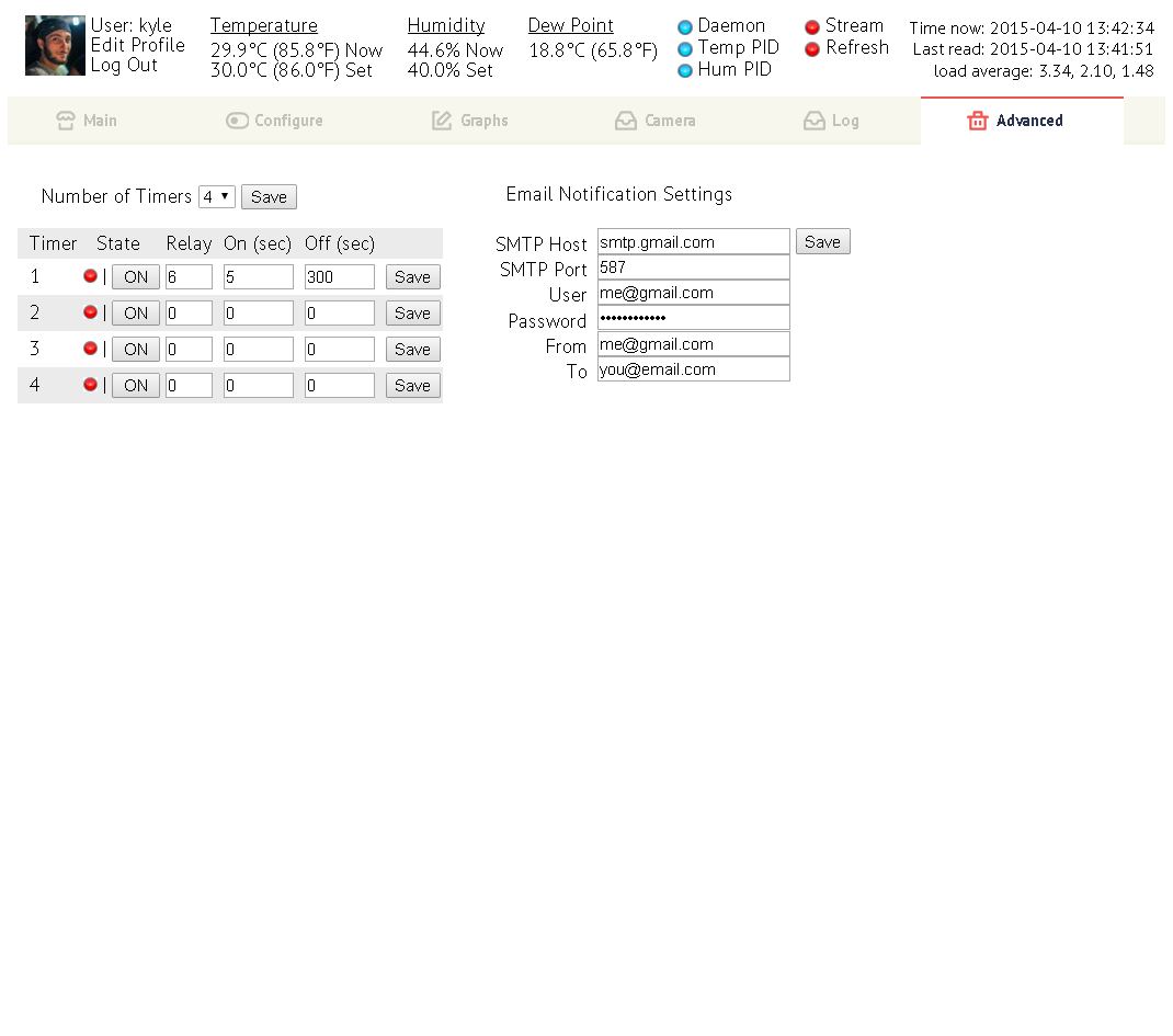
Support for up to 8 simple timers (define on duration, off duration)
True PID control for temperature and humidity regulation
Support more humidity & temperature sensors (DHT11, DHT22, and AM2302)
Multi-sensors support to regulate multiple environments
TempFS to reduce writes to and extend the life of the SD card
Lock files to prevent sensor read and file access conflicts
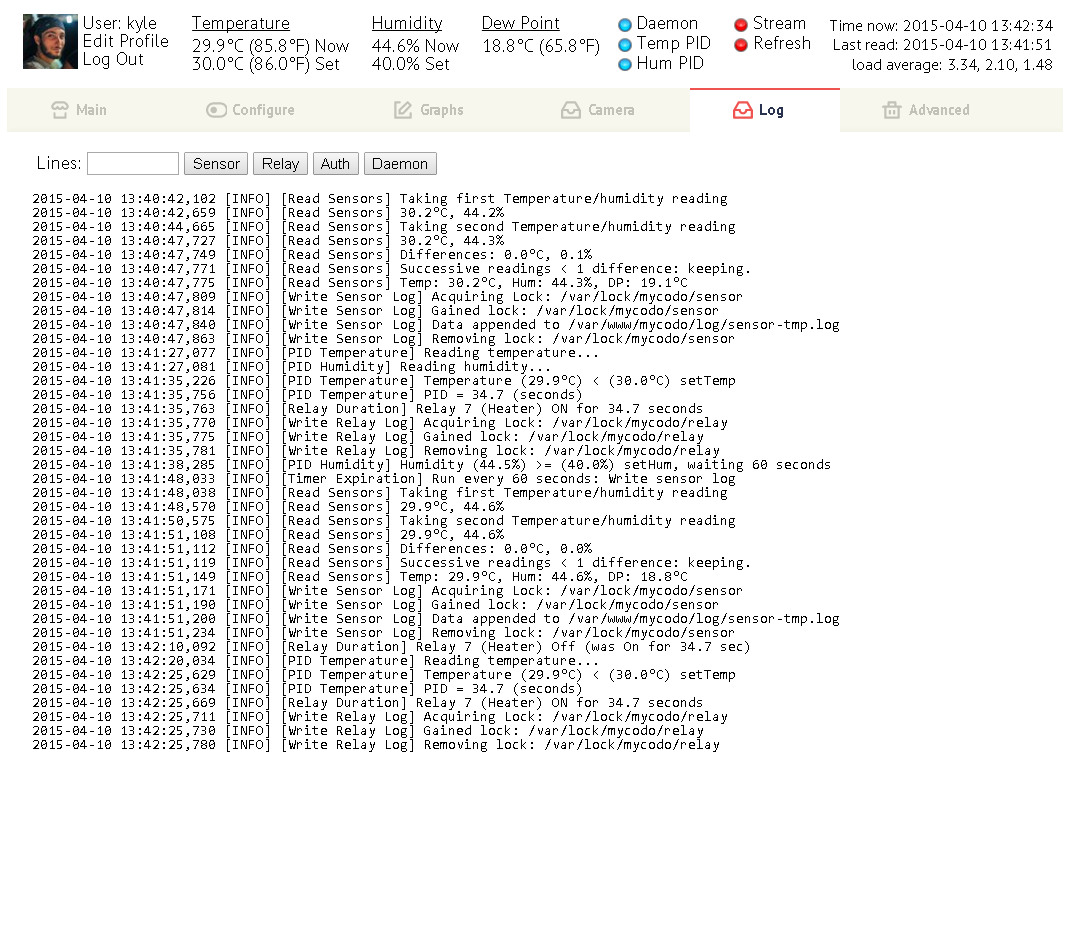
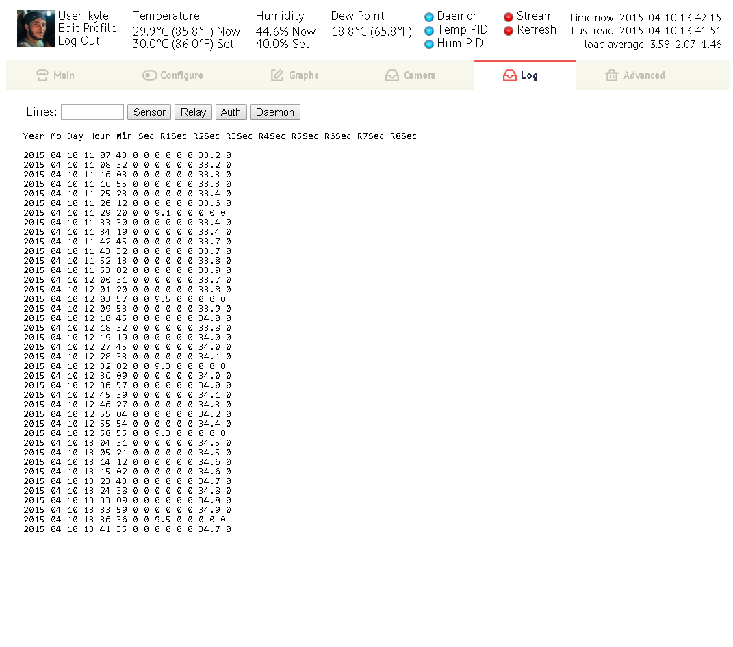
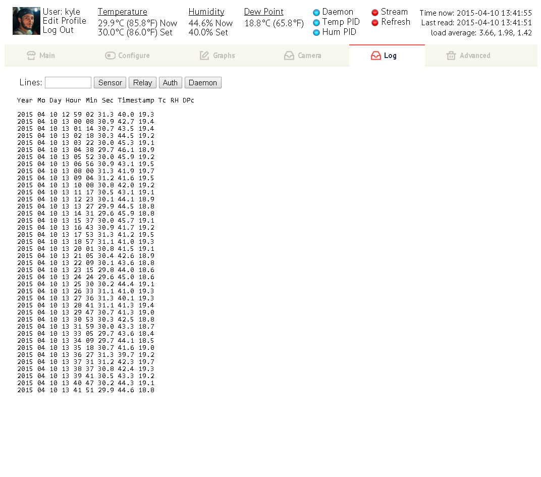
New logs to view: login authorization, daemon, sensor, and relay logs
Generate new types of graphs
Combined: generate a graph combining all temperatures or humidities
Separate: generate a graph of the temperature, humidity, and dew point of each sensor
Define graph image width (custom graph only)
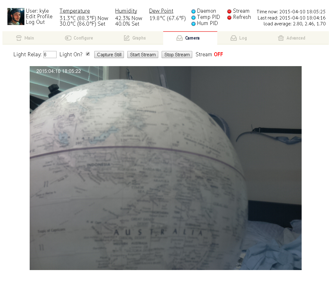
Acquire still image or stream live video using the Raspberry Pi camera module
Set relay (light) to be burned on while camera is capturing
New web interface
Tabs allow everything to be loaded on one page
Easy change any variable in the configuration file
Login Authentication (written by php-login.net)
Optional cookie to keep session authenticated
Guest account for viewing only (no config changes permitted) (user: guest, password: anonymous)
Authorization log of successful and unsuccessful login attempts
User profile, gravatar support (from email), lost/forgot email password reset
version 2.0
All software running on a Raspberry Pi version 1 Model B
Support for the DHT22 digital humidity and temperature sensor
Manual or automatic switching of up to four 120-volt AC relays
Automatic operation by simple proportional temperature/humidity regulation
Temperature, humidity, and relay state-change logging
Basic web interface
Configure variables related to sensor reading, log writing, and graph generation
Generate custom graphs of current and past data
Presets of pre-defined time periods (past 1 hour, 6 hours, 1 day, 3 days…)
Specify specific time period to generate graph
version 1.0
Read humidity & temperature sensor with an ATMega
ATMega connected by serial USB to a network-enabled computer running linux
Linux periodically read humidity/temperature sensor and write log
ATMega modulate relays for simple proportional humidity/temperature regulation
Simple web interface to view historical data and generate graphs with gnuplot
Hardware (Bill of Materials)
| Part | Quantity | Purchase |
| Raspberry Pi 1 B (it’s now recommended to use the newer Raspberry Pi 3 B+ or Raspberry Pi 4) | 1 | Amazon, Amazon |
| Micro SD Card (32 GB) | 1 | Amazon |
| Raspberry Pi V2 Camera Module | 1 | Amazon |
| 5-volt 2-Amp DC Power Supply (CUI VOF-10-5 in photos) | 1 | |
| 8-Channel Relay Module (Mechanical relays at 10 Amps max each or Solid-state relays at 2 Amps max each) | 1 | Amazon, Amazon |
| Crydom 40-Amp Relays | 2 | Amazon |
| Humidity/Temperature Sensor (HTU21DF, AM2315, SHT31, or BME280, etc.) | 1 | Amazon, Amazon, Amazon, Amazon |
| Electrical Box Enclosure | 1 | |
| 8-Outlet Power Strip | 1 | Amazon |
| Nuts, Bolts, Standoffs, Wire | 1 | |
| Terminal Blocks and Jumpers (4-Position, 6-Position, and 8-Position) | 1 | Amazon, Amazon, Amazon |
| Growing Gourmet and Medicinal Mushrooms by Paul Stamets | 1 | Amazon |
Construction
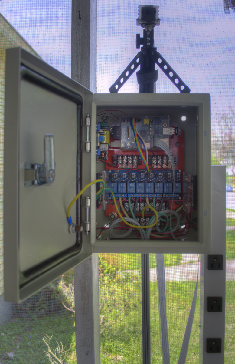
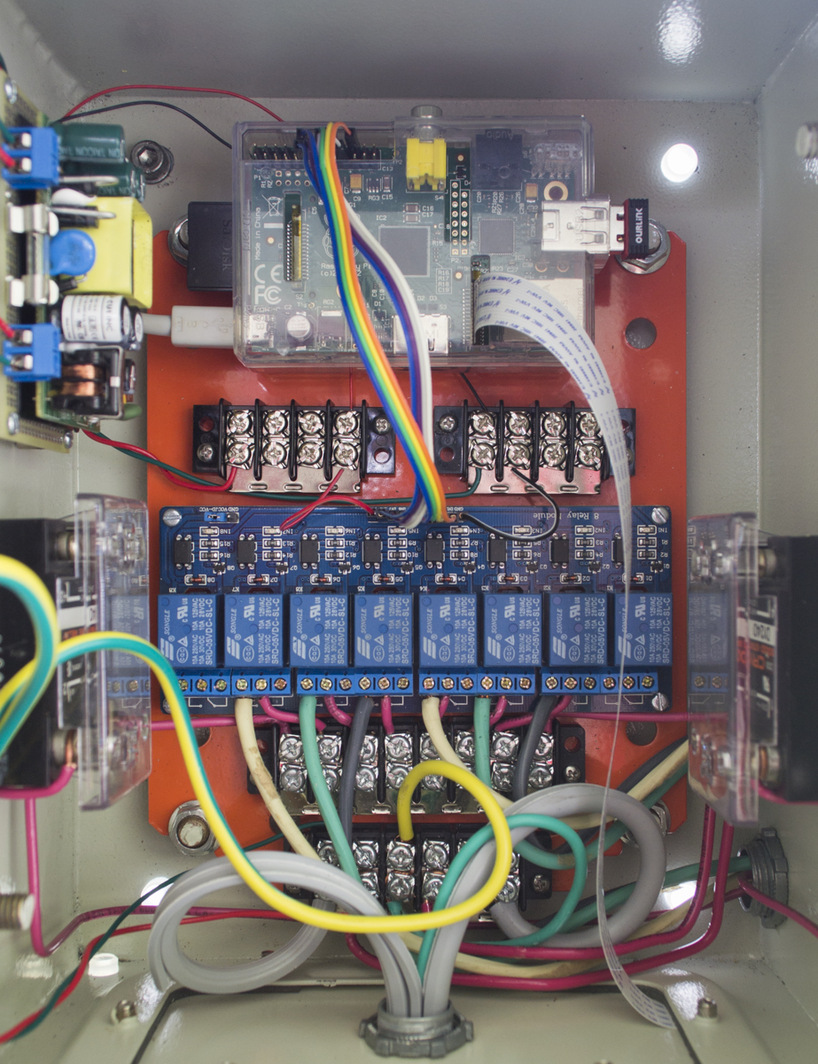
I started with a lockable electrical box with ground connections on the body and door. Holes were drilled and knockouts were removed to feed 12-gauge wire between the 8-outlet strip to the box. The relay board, RPi, and terminal blocks were bolted to the back plate, with the RPi and relay board raised off the plate with stand-offs. The 5-volt power supply was soldered into a circuit with and an in-line 2A fuse and screw-terminals. The terminal blocks were used to distribute power through the relay switches on the relay board, and the 5-volt DC to power the RPi and relay coils. I chose to use six of the eight 10-amp relays to directly switch six outlets, and the remaining two 10-amp relays to control the 40-amp relays, which were wired to switch the remaining two outlets. This allows up to six devices to be used that have a maximum current draw each of 10 Amps and two devices up to 40 Amps. Last, the main box, door, outlet strip, and outlets were grounded.


Sensor and Relays
The DHT22 sensor has pins for ground, power, and data. Data connects to a GPIO and though a 10k resistor to DC+. I’m using a Sainsmart 8-relay module, however any opto-isolated relays should suffice. In the case of this relay board, JD-VCC should be connected to the power supply and VCC connected to the RPi VCC to ensures proper isolation of the RPi. The newest version of Mycodo supports better humidity/temperature sensors than the DHT22, including the BME280, AM2315, and HTU21D.
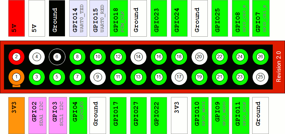
Each relay control pin on the relay board will need to be connected to a GPIO pin on the RPi. Ensure your relays are properly opto-isolated (or otherwise have a very low input current) to prevent drawing too much current from the RPi. Avoid connecting to GPIOs that are normally HIGH or LOW at boot, as this can inadvertently turn your relay on until the GPIO initialization script is executed. Depending on the relay board or custom circuit you end up using, your relays will turn on with either a HIGH (5-volts) or LOW (ground) signal from the RPi. This relay board energizes the relays when a LOW signal is provided. Upon bootup, the voltages of the GPIOs connected to the relays are floating, meaning they are neither HIGH nor LOW but somewhere in between. The initialization script sets all connected GPIOs to output, then sets them LOW from their floating state.
Software
- Mycodo (source code on GitHub)
There are two main components of the Mycodo system, the Mycodo daemon and the Mycodo client. The daemon performs all critical tasks, such as periodically reading sensors, writing logs, reading/writing the configuration file, turning relays on and off to regulate temperature, humidity, and airflow, among other functions. The client application issues commands for the daemon to carry out. This is the link from the web interface to the daemon, communicating configuration changes, manual relay switching, modifying automation, and other information. Common usage is to continually run the daemon in the background and use the client to communicate with the daemon.
Installation
I’ve taken the install instructions out of this publication because this is an old version of Mycodo. To find the install instructions to install the latest version of Mycodo, go to github.com/kizniche/Mycodo.
Daemon
mycodo.py: Reads sensors, writes logs, and operates relays to maintain set environmental conditions.

Usage:  mycodo.py [OPTION]...

Options:
    -d, --daemon v/s w/i/d
           Start program as daemon that monitors conditions and modulates relays
           v enables log output to the console, s silences
           Log level: w: >= warnings, i: >= info, d: >= debug
    -h, --help
           Display this help and exit

Default: mycodo.py -d s w
Debugging: mycodo.py -d v d
Client
mycodo-client.py: Client for mycodo.py (must be running in daemon mode -d)

Usage:  mycodo-client.py [OPTION]...

Options:
        --modtempOR sensor state
           Temperature PID control: 0=enable, 1=disable
        --modtempPID sensor relay set p i d period
           Change Temperature PID variables
        --modhumOR sensor state
           Humidity PID control: 0=enable, 1=disable
        --modhumPID sensor relay set p i d period
           Change Humidity PID variables
        --modrelaynames name1 name2 name3 name4 name5 name6 name7 name8
           Modify relay names (Restrict to a maximum of 12 characters each)
        --modrelaypins pin1 pin2 pin3 pin4 pin5 pin6 pin7 pin8
           Modify relay pins Using BCM numbering)
        --modrelaytrigger trig1 trig2 trig3 trig4 trig5 trig6 trig7 trig8
           Modify the relay trigger states (0=low, 1=high; turns relay on)
        --modsensor sensor name device pin period activated graph
           Modify sensor variables
        --modtimer timer state relay on off
           Modify custom timers, State can be 0=off 1=on, on/off durations in seconds
    -m, --modvar name1 value1 [name2] [value2]...
           Modify any configuration variable or variables (multiple allowed, must be paired input)
    -r, --relay relay state
           Turn a relay on or off. state can be 0, 1, or X.
           0=OFF, 1=ON, or X number of seconds On
    -s, --sensor pin device
           Returns the temperature and humidity of of the DHT sensor on GPIO pin
           Device options are DHT22, DHT11, or AM2302
    -t, --terminate
           Terminate the communication service and daemon
    -w, --writelog sensor
           Read from sensor number and append log file, 0 to write all.
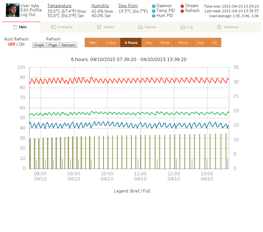
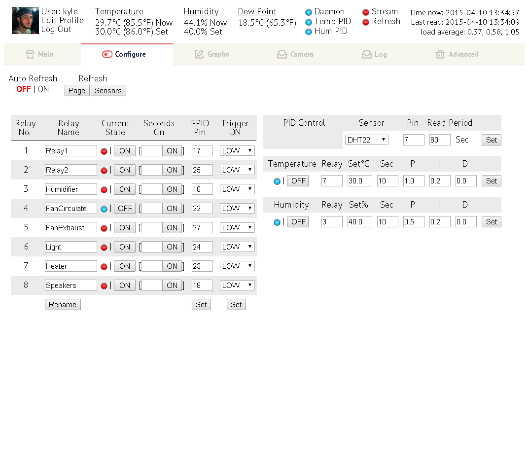
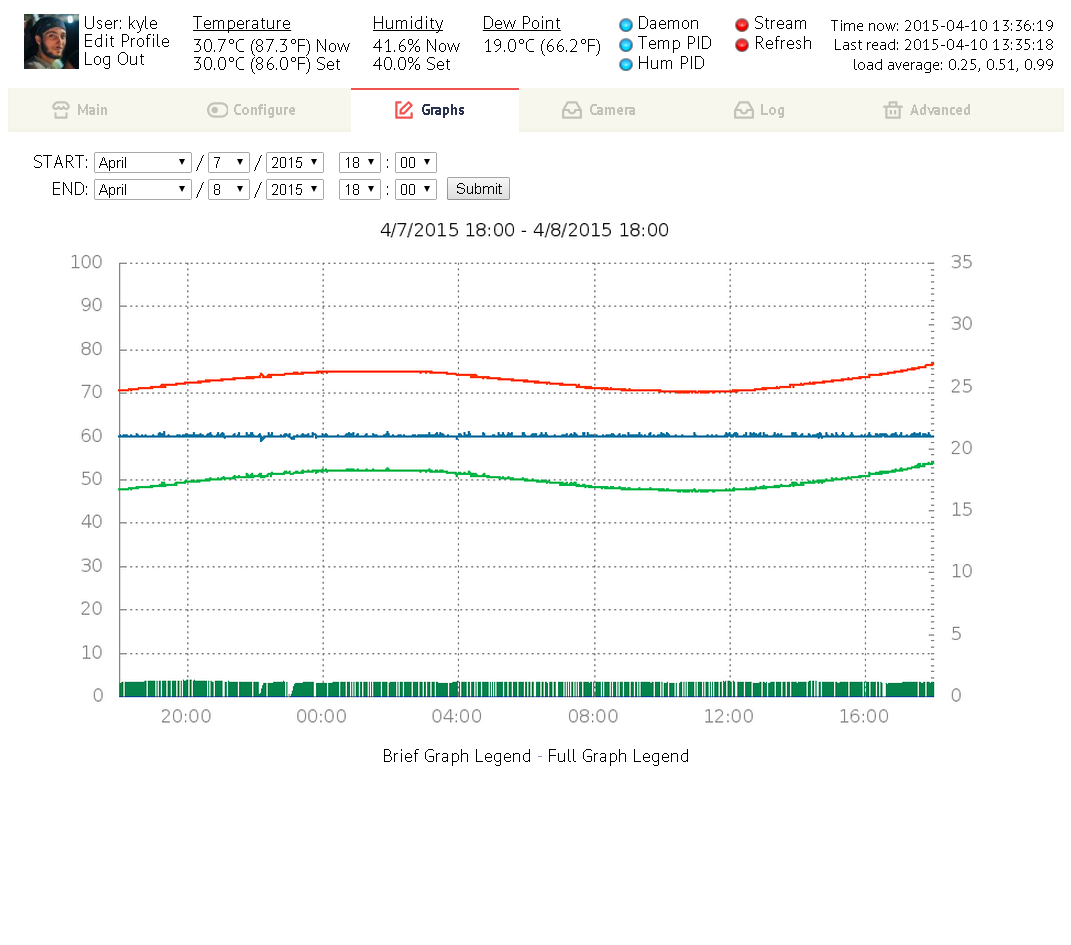
Screenshots
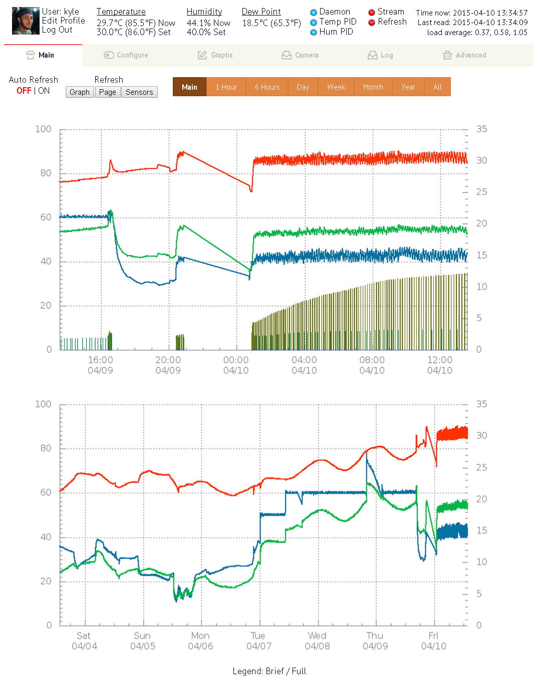
The web interface provides a way to view and change all aspects of the system as well as generate graphs from current and past sensor data.

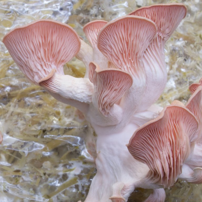
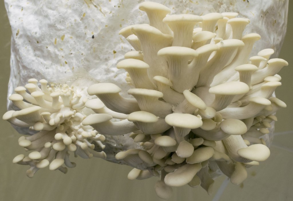
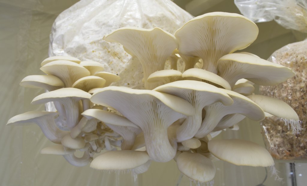
The Fruits of My Labor
What project would be complete without some great mushroom photos? I haven’t had a chance to grow with this new controller yet, so these are from a previous harvest. I hope you enjoyed this trip though automated mushroom cultivation.
A Call for Experimentation
Well, you made it to the end of the page. I may end up regretting this, but for now, for science, you can log in to my control interface as a spectator with the userguest and passwordanonymous at [redacted]. If you notice any discrepancies or issues with any of the content, please leave a comment below or use the contact form in the top menu.
Update (4/12/2015)
As expected, my RPi has had an onslaught of attempts to breach the security since featured on hackaday.com. However, it has remained strong.
Here’s a small excerpt of my auth.log. It’s been steady like this for the past 8 hours, before unleashing fail2ban to monitor my auth.log and manage bans in iptables.
Apr 12 13:55:30 sshd[11026]: Failed password for root from 182.100.67.113 port 34509 ssh2
Apr 12 13:55:31 sshd[11034]: Failed password for root from 43.255.190.162 port 35661 ssh2
Apr 12 13:55:31 sshd[11030]: Failed password for root from 221.229.166.27 port 44507 ssh2
Apr 12 13:55:32 sshd[11018]: Failed password for root from 43.255.190.183 port 49051 ssh2
Apr 12 13:55:32 sshd[11017]: Failed password for root from 43.255.190.156 port 50272 ssh2
Apr 12 13:55:34 sshd[11030]: Failed password for root from 221.229.166.27 port 44507 ssh2
Apr 12 13:55:34 sshd[11018]: Failed password for root from 43.255.190.183 port 49051 ssh2
Apr 12 13:55:35 sshd[11043]: Failed password for root from 43.255.190.156 port 45633 ssh2
Apr 12 13:55:36 sshd[11018]: Failed password for root from 43.255.190.183 port 49051 ssh2
Apr 12 13:55:37 sshd[11014]: Failed password for root from 210.220.248.162 port 42025 ssh2
Here’s an excerpt from iptables after fail2ban:
Chain fail2ban-ssh (1 references)
target     prot opt source               destination
DROP       all  --  210.220.248.162      anywhere
DROP       all  --  221.229.166.27       anywhere
DROP       all  --  43.255.190.183       anywhere
DROP       all  --  182.100.67.113       anywhere
DROP       all  --  43.255.190.156       anywhere
DROP       all  --  43.255.190.162       anywhere
DROP       all  --  43.255.190.145       anywhere
DROP       all  --  218.87.109.60        anywhere
DROP       all  --  43.255.190.160       anywhere
DROP       all  --  43.255.190.177       anywhere
DROP       all  --  43.255.190.161       anywhere
DROP       all  --  43.255.190.151       anywhere
DROP       all  --  43.255.190.186       anywhere
DROP       all  --  43.255.190.150       anywhere
DROP       all  --  222.186.51.228       anywhere
Here’s an excerpt from the Mycodo auth log. Its formatted by CSV, with the entry after NOUSER being the user name that the user attempted to log in with.
2015 04 12 08:16:31, NOUSER, fungi, 23.233.2.92
2015 04 12 13:39:44, NOUSER, #, 80.109.109.80, chello080109109080.16.15.vie.surfer.at
2015 04 12 13:39:50, NOUSER, --, 80.109.109.80, chello080109109080.16.15.vie.surfer.at
2015 04 12 13:40:02, NOUSER, ' or '1'='1, 80.109.109.80, chello080109109080.16.15.vie.surfer.at
Update (7/02/2015)
Thank you to all who tested Mycodo while I enabled guest login on my system. I’ve received a lot of feedback that has greatly improved the system. Guest access is currently disabled while I test new features with the 3.5 experimental branch.
Affiliate links
I participant in the Amazon Services LLC Associates Program, an affiliate advertising program designed to provide a means for sites to earn advertising fees by advertising and linking to Amazon.com, and I make a commission for sales made through affiliate links posted on this website.
Nice work! I have an outdoor mushroom farm near Cincinnati, OH USA but have considered also cultivating indoors and incorporating an RPi to read sensors and control the environment.
My winter project had an RPi with thermocouples reading the temperature of the water leaving and returning to my radiant heat boiler. Next year I intend to have the RPi turn off and on the various zones in my house. My RPi just dangled from the wall all winter. Your enclosure and wiring job is downright sexy and I think I may use it as inspiration and a model for my system next year!
Keep up the strong work!
Thanks for the kind words. I’m glad my project has inspired you. It sounds like you’re on your way to an automation addiction like myself. I’d like to see your system when you get it operational. Good luck!
Please correct “/etc/apache2/sites-avalable/default” to “/etc/apache2/sites-available/default”.
If rpyc missing, run “sudo pip install rpyc”.
I encounter problem when use “mycodo.py -s”. This file hase both … opt in (“-r”, … in line 376 and line 421 without … opt in (“-s”…
Thank you for finding these mistakes. I’ve amended the install instructions with the spelling correction and to include RPyC, and pushed the mycodo.py update to GitHub.
I usually hate videos, because what they show in 15 minutes can be learned from reading written instructions in one minute.
Yours was different. I watched all 5+ minutes with interest and learned more than I could just from reading alone.
Looking forward to future updates and projects!
Your command to set permissions for www to use the camera likely doesn’t work as expected. You are running echo as superuser, but redirecting its output as your non-superuser user to a file for which you presumably do not have write permission. One way around this is to pipe the output of echo to tee running as root (“echo ‘foo bar’ | sudo tee /path/to/restricted_file”). Tee reads from standard input and writes what it reads both to its standard output and to a file.
I do recall something weird surrounding that command, like what you described. I must have forgotten what I actually did to get it to work when I wrote the documentation. Thank you for catching that and for the explanation.
Hi Kyle loving your work…would really like to implement this type of tech into my horticulture degree projects but have no clue about computers really, growing plants is my thing, any help or advice would be much appreciated.
Dan,
I would recommend getting in contact with a local hacker/maker space and express your interest in utilizing/developing skills in these areas. I’ve done most of the leg work as far as programming and suggesting a good hardware combination, so you’ll just need to find the right people to help you along. I have quite a bit on my plate right now with graduate school, but I can try to help with any issues you come across. Just use the Contact form at the top of the page to get a hold of me.
“And I’m not sure of the approach these two people are taking, but here’s an excerpt from my Mycodo auth log. ”
SQL Injection to bypass authentication. I don’t know why though, the source is available so anybody could see if there was a vulnerability.
Hey Kyle,
Under your header for setting up the DAEMON,
There is no /init.d in folder /mycodo however it is in /mycodo/source.
Anyway, all set up and hardware/software seem to be working fine, thanks for the learning experience.
Watching the change logs have given me the impression that it is pretty stable so far. How would I go about updating to the latest code in the future?
Kyle,
You are correct, I missed the source directory. That should be corrected now.
I believe it is at a fairly stable state. I’ve done quite a bit of bug testing in the weeks prior to and shortly after this release.
As for updating to the latest code, because I’m not sure how it will progress from here and I’m not too familiar with programming for proper backwards-compatibility, I would suggest cloning the GIT repository into a new folder and copying the settings (or config file) and logs over. I’ll look into this area more (which I need to be more knowledgeable about) and develop an “Updating from a Previous Version” section for the README.
From Brazil,
Nice work! Very, very cool your Project.
Hi Kyle,
Greetings from Hungary…
What a great project!! Your design and attention to detail is fantastic. I have been looking for similar projects on the web that might be easily adapted to my cheese-aging system, but this looks the best so far. I can’t wait to get down to the basement (if time permits, but it does not really cooperate) and give your setup a test. Of course it will include several key differences, e.g. I use low-voltage fans with PWM, etc.
I have one question out of curiosity: what is your experience with the DHT sensors? I use AM2302, and when I originally tested, the readings became ‘very’ deteriorated when my cabling extended 2 meters. For me, it is not really a problem, but in your setup, it looks that the sensor should be even farther from the RasPi.
Keep up the great work!
Zsolt
PS: I also agree with the comment above on your video… very good and informative
Zsolt,
Glad to hear! I’ve always wanted to get into cheese-making. One day it will happen.
As for the AM2302, it is merely the DHT22 sensor and resistor encased in a housing. I currently have my DHT22 connected with roughly 2 meters of wire. I haven’t used anything longer, however I did just receive 2 more DHT22 sensors in the mail for experimenting with a multi-sensor setup. The problem may be with the voltage drop that occurs with DC and long wires. You may have to increase the voltage or reduce the gauge of the wire to reduce the voltage drop. Though, this is just based on my knowledge of DC voltage. I’ll run a few experiments and see if I can figure out.
Hey Zsolt,
Im curious if you were successful with using PWM fans in your setup? Were you able to add fan speed control to the web interface? I have been looking in to different ways on how this could be done. There are a few videos of people using PWM fans to keep the Pi cool but the information is scarce and so far most of it is controlled through command line. I am going to do something a little simpler for now but I will probably continue to research this some more.
Cheers
congratulations on your project.
i have a question. how many square meter of mushroom cultivation this system can control?
Will,
With the current state of the system, only one sensor can be used for monitoring, which limits the area that can be efficiently monitored. The beauty of the system is that is can handle both small and large growing areas. To switch from one to another you would simply need to adjust the PID of the controllers. I was cultivating with a combination of straw in bags and grain in open containers, so calculating the area would be a little difficult, but I would estimate that I as growing on roughly 2 square meters of area, however the closet I was growing in could hold a lot more. I’m in the process of updating the code to support multiple sensors at the same time and the ability to assign different relays to each sensor.
Great! KyleGabriel
I am going to start my project in three areas each of 3 mts square. first zone incubation and the others two for grow.
how much cost this system, you can guide me.
by other hand i have a question, why you install the web server into raspberry pi?. You have an estimate for the use of ram and procesor with the web server run ?
This was my Digikey order:
Quant.  Part No.        Part                                $/Per   $/Tot
1       102-2039-ND     PWR SUPPLY 10W OPEN 5V 2.0A         14.86   $14.86
4       8128K-ND        CLAMP CABLE INSULATED .625" DIA     0.59    $2.36
1       283-4019-ND     TERM BLK 20A 8CIRC UL CSA           7.70    $7.70
1       283-4018-ND     TERM BLK 20A 6CIRC UL CSA   	    6.44    $6.44
2       1546307-4-SI-ND CONN BARRIER BLOCK 4CIRC 9.53MM	    2.76    $5.52
3       WM4244-ND       TERM JUMPER ON EDGE SQUARE 2POS     0.44    $1.32
2       WM9718-ND       JUMPER EDGEON SQ 4POS .375 CNTR	    1.43    $2.86
1       WM5017-ND       CONN JUMPER TERM EDGEON 8POS        2.30    $2.30
10      AE10867-ND      HEX STANDOFF M2.5 BRASS 10MM        0.28    $2.80
20      KEY1048-ND      MACHINE SCREW PAN SLOTTED M2.5      0.317   $6.34
2       ED2609-ND       TERM BLOCK 5.08MM VERT 2POS PCB     0.42    $0.84
3       507-1228-ND     FUSE GLASS 2A 250VAC 5X20MM         0.22    $0.66
2       486-2019-ND     FUSE CLIP CART 250V 6.3A PCB        0.11    $0.22
40      KEY1214-ND      MACHINE SCREW PAN PHILLIPS 4-40     0.087   $3.48
                                                 Digikey Subtotal   $57.70
In addition to Digikey, I sourced these elsewhere:
So, in total, it was around $160 USD
As for why I installed a web server, it just seemed like the easiest interface to work with considering my knowledge of PHP/HTML. It also permitted remote access from any computer with a web browser and internet. The CPU and RAM load will depend on the number of users on the server, but for practical use (1-3 users), this will be relatively low. With that being said, I’ve tested this system with a peak of 30 – 40 (guest, view only) users and it appeared to operate just fine, albeit a bit slower. This RPi is dedicated to running just Mycodo at the moment, so it has no problem with system resources.
thanks so much i am going to building the system, i will be in touch.
you are very kind.
Hi Gabriel is possible that you share me the schema or drawings of project?
Unfortunately, I have none. I made a quick sketch of how I though the components were going to be laid out on back plate of the electrical box, but I did something completely different when I actually had the components in front of me (you can see in the first part of the video). The schematic for the power supply was so simple, I didn’t make one… It essentially has the (-) and (+) AC connecting directly to the power supply AC inputs and the output 5+DCV go through a 2-amp fuse before connecting to the terminal block, and the ground DC connected directly to the terminal block. The relay board had ground connected to ground, 5+DC to the 5+DC, and each trigger wire connected to a free GPIO on the RaspberryPi. If you have any specific questions about wiring, let me know and I’ll try to help.
Hi, thanks for your great software , I think there is a minor mistake in the documentation:
If set up correctly, the following command should display temperature and humidity.sudo /var/www/mycodo/cgi-bin/mycodo.py -r"
I think that´s wrong, and the right cmd should be sudo /var/www/mycodo/cgi-bin/mycodo.py -s (sensor #) but sudo /var/www/mycodo/cgi-bin/mycodo.py -s 1
doesn´t show anything in my setup (besides it´s working fine and updating the logfile)
Thanks for spotting that. I’ve been updating the Mycodo code a lot recently, and I moved that command from the daemon (mycodo.py) to the client program (mycodo-client.py). I’ve updated the post and pushed an update for mycodo.py and mycodo-client.py to github. Sensor data can now be read with the command mycodo-client.py -s PIN DEVICE. There’s a description in the post and if you issue the command mycodo-client.py –help
Hi Kyle,
Finally I had a chance to setup my RasPi with a dry run of your system.
It works now almost perfectly, except that some graphs are not shown, but I believe there is simply not enough data points to show … yet.
My experience with your instructions, is that they are very clear and easy to follow. I had a small hiccup setting up MySQL and User Login, ‘http://127.0.0.1/phpmyadmin’ did not work from my PC as instructed, but’ http://YOUR_IP/phpmyadmin‘ did. The same happened with all instances of 127.0.0.1.
The other point that was not immediately clear is under Sensors and Relays, you say …start up the daemon with ‘sudo service mycodo’ start.
By following the instructions, it simply does not start, the service is not yet set up. The later section under Daemon should be completed first (with or without editing crontab).
Now I have to figure out how to adapt it to my current hardware …
Thank you for sharing this great project!
Zsolt
Zsolt,
You’re correct, the graphs far into the future will look blank until some sensor data has been generated. You can test it by adding a sensor data entry above the others that has a date a few months prior, then it should connect to the most recent data points (as a straight line to the latest data, on the graph), if you want to test the long-duration graphs.
That is a problem with the init.d section… I’ve edited the daemon startup command in the post so it will work before init.d is set up.
I’m not sure why 127.0.0.1 on your system isn’t bound to localhost, but glad you figured it out.
Out of curiosity, what type of hardware are you adapting to? Different sensors or something completely different?
Hi Kyle,
Maybe the word adapting is not correct… I use 5V from the PSU of the Rpi for my little fans, which has a simple transistor circuit to turn them on/off . These probably will work the same way as for your relays, the GPIO pin for the relay will similarly turn the fan on/off. Although I needed to use PWM to decrease air-flow, since the volume of the refrigerator used as the aging chamber of the cheeses is quite small, even running for a few minute at full speed with a 40 mm PC fan can decrease the humidity severely.
The bigger mod will be the hack of the temp-control of the refrigerator, and if it’s done, to see what should be modified (if any) for controlling cooling, rather than heating.
Zsolt
Zsolt,
Sounds like a nice project. I’m sure the humidity PID controller as it stands can adequately use your PC fans to regulate humidity. Depending on what P, I, and D values you use, it should be able to regulate without PWM. However, I’m not trying to dissuade you from forging your own path to get it to work the way you like.
For the cooling, because the refrigerator is insulated, PID may be overkill. A solution could be as simple as adding the following to mycodo.py, in the while loop of daemon() (where the other timers are located):
# Turn cooler on if above 10C, off if below 5C (check every 60 seconds) if int(time.time()) > timerCooler: read_sensors(1, sensorNumber) # Read sensor in fridge if tempc[sensorNumber] > 10: # If getting too hot relay_onoff(relayNumber, 1) # Turn fridge relay on elif tempc[sensorNumber] < 5: # else if getting too cold relay_onoff(relayNumber, 0) # Turn fridge relay off timerCooler = int(time.time()) + 60 # reset timerHi Kyle,
Thank you for the advice. This was the way I had my program setup originally. I agree that the well-insulated refrigerator makes the complicated regulation unnecessary. The place where it should go into your code is really helpful, thanks. Actually the tight insulation (door seal) gave me another problem that was not there in the concept prototype: even the smallish fan makes a vacuum making it hard to work against. I need to figure out a good way ventilate when the fan is on.
On the other hand, the graphs are still not working. The error message is “The image http://192.168.10.111/mycodo/image.php?span=separate6h&mod=5571d3a95b664&sensor=1 cannot be displayed because it contains errors”. Checking the directory /var/log/mycodo/images, only files with graph-main prefix exists, other than the legend files. I was trying to run graph.sh manually, but could not get the parameters work. Do you have any suggestion what needs to be changed?
Thanks,
Zsolt
With the help of Zsolt and another person who tested an experimental mycodo.py, a major bug preventing graph generation was fixed and pushed to github. Thanks.
Hi Kyle,
Thank you for your continued e-mail help to sort out my issues.
I cannot say enough times and loudly this!
Everything works great now. The only issue I have right now that I had another case of “runaway relay”. At this time, I was not even playing with the hardware, but apparently the system just stopped. Due to WLAN issues, I could not detect it for about three hours, and then my fridge was full of mist.
Is my understanding correct that on reboot every relay should be set its programmed state? Including the ones that are set for the sensor PIDs? Since I have PCBs set up to control up to three separate chambers, I do not have the luxury to select only GPIO pins that are not normally HIGH or LOW upon boot, I wired almost all of them. Could this be the problem that the GPIO for the humidifier relay is on a boot time HIGH pin, and it is not turned off?
I found an example to modify GPIO boot state on a site, but if the boot HIGH is not the reason, it may not worth the effort. In any case, everything is OK now, so let’s hope that after being done with the experimentation, no more cold cloud will occur (which makes everything wet and needs to be wiped dry, including the cheeses).
Zsolt
Zsolt,
Sorry to hear about your wet cheeses! I will do my best to fix a runaway relay problem, as I consider this a critical issue.
You are correct about the relays being initialized at startup. For most GPIOs, their state is floating or set LOW upon boot, however a few are set HIGH. I ran into this problem because with 3 sensors, 8 relays, and 3 being used to control a RF remote (different project), I was forced to use at least one GPIO that’s pulled HIGH at boot. I created the program GPIO-initialize.py to run at startup (@reboot line in cron) and reference mycodo.cfg for the relay trigger state, then set the associated GPIO to the opposite. The trigger state defines the signal that turns the relay ON. If the relay turns on when the input signal is LOW (0 volts), relay1trigger = 0, and the GPIO associated with relay 1 will be set HIGH (5 volts) to turn it OFF, when GPIO-initialize.py is run. This ensures that upon startup all GPIOs connected to relays are set to output the proper signals to turn all relays OFF. If you have a trigger state set improperly, GPIO-initialize.py will set the relay ON at boot instead of OFF. I assume that because the rest of your system works, you didn’t misconfigure this.
You mentioned that the system stopped. I haven’t had any runaway relays recently, but many times throughout early development I was able to track down the cause of a runaway relay to either the system hanging or crashing while the relay was on. If it continues to happen, I’d like to ask you to run the daemon in debug mode and attempt to recreate the issue, then send me all logs and any errors. I’ve had my system running 24/7 for the past few months (the address to access my system is still at the bottom of the publication) to try to find any bugs that may take exceptionally long or require rare scenarios to present themselves.
Also, if you have any custom code added anywhere, you can email it to me and I’ll check to see if I notice any problems or potential conflicts with any other part of the system.
Tanks Kyle,
I really appreciate your attention. I move d the cheeses to another container for the time being, so no problem with them.
I think that the relay triggers are set OK for boot.
On the other hand, while I did not try to recreate the problem, it happened again. This time the conditions can be determined, since I made a change, and then the relay stuck ON. What I did was that I wanted to start to play with the PID settings (although I previously had no experience in this). First, yesterday I changed the HUM_PID interval to 60 secs (the default 10 sec seemed to short for me, reading through the Wikipedia article on PID, I though that for manual tuning I need longer settings). So after a while the humidity dropped back below 99.9%, and the values normalized (with a quite big oscillation, but this is not my main concern now…). Then this morning I reduced back the HUM interval to 10 secs, to see what happens with the oscillations. In a few minutes, the humidity went up 99.9%, and the relay stuck ON! I send you an email with my logs for the relevant time frame. The PID settings that time calculated longer than 10 seconds on-time for the HUM relay, can it be the problem?
I manually set the relays through SSH and now waiting the sensor to dry out. So I have time … so let me have a few questions.
Can you tell me what are the blue and red dots in the webinterface/config page? I though that it is the status of the relay, but in that case it is not updated when the relay changed from SSH. Is it a planned behavior?
Copying over the log files, I noticed that they increase steadily. I know that storage gets unlimited these days, even for the RasPi, so even file sizes of lots of MBs should not be a problem for filling up the SD card. On the other, log file corruption would make presenting the historical data impossible. Maybe some regular backup would be useful. Or I used earlier logger objects for data storage, it works quite good with file rotation, either based on file size or time.
I’ll keep you updated if anything relevant happens.
Zsolt
Thanks for the update. Whenever a setting related to the PID is changed, the whole PID thread is stopped then started again, so I’m not sure during what precise time in the events of either pre, during, or post PID restart that the issue is occurring. As I mentioned in reply to your email, I’ll need to you have the daemon running in debug mode (mycodo.py -d v d) to pinpoint the exact time of the issue, and that should help me find where in the code there’s a problem.
The duration that’s calculated for the PID can be from a lot of factors. If you’re only using the P and the I, and D are set to 0.0, the 10 seconds would merely be proportional to the difference between the actual and desired humidity multiplied by P, so if your actual humidity is 70% and it’s desired at 80%, and P is 1.0, then the PID output will be 10.
The dots: Red is off, blue is on. Because the web interface doesn’t continually update, the blue and red only indicate at the time the web interface was refreshed. So, if it refreshed while a relay was on, it would show blue, however it will remain blue after it has turned off because the page hasn’t refreshed.
“[the dot] is not updated when the relay changed from SSH”
The dot under the relay’s “current state” is changed based on what’s returned from the C program “/usr/local/bin/gpio -g read [PIN]” so it is checking the state of the pin in that moment. You should see the image change if you’re using the command “gpio -g write [PIN] [0/1]”
On a side note: You actually made me find a bug just now in double checking this (I don’t think this would have affected you). It was checking the state of the pin without considering what the trigger state was, which could cause the images to display opposite of their current state if you had a HIGH trigger state. I’ve pushed an updated index.php to github. Download the new index.php and see if it fixes your red/blue image problem, otherwise I’m stumped.
The Logs: There is a timer in the daemon to automatically backup logs from their temporary location to /var/www/mycodo/log every 6 hours or when the daemon is signaled to terminate. As long as you’re not running the daemon in debug mode all the time, the log sizes should stay relatively small. I haven’t done anything with backing up with compression because it would get more challenging to read the logs for graph generation. If you have any suggestions, I’d like to hear.
Hi Kyle,
Thanks for the detailed answer, and the email, too.
Right now I don’t have too much time to play around with the system, but at least it has stabilized, although with high level of oscillation in humidity. I started to think about it, and getting the impression that it is caused by the hardware itself, i.e. the fridge. When it turns on, the water freezes out on the back, thus lowering the humidity. It causes the humidifier to turn on, adding more vapor to the small volume. When the fridge cools down, the backside melts, the water starts to evaporate and is in part added back to the humidity. This theory seemingly is backed by the temperature readings, the smaller oscillation of the fridge control mechanism is paralel with the humidity oscillation.
It looks that the relay is fine, and if I’ll have time (never?) I’ll go and hack the fridge control and connect it to a relay and try the PID your software provides to see if the oscillation decreases.
I’ll try to download the updated index.php to see how it works.
For the logs I only meant that if the system running continuously for several years, the regular log file increases continuously. If it is kept as a single big file, and the file is corrupted, all the historical data is lost. Am I incorrect in taht?
Zsolt
I’ve contemplated a few times using
logrotateto backup and compress log files, however the graph generation relies on plain text. I suppose I could uncompress and read, but I’m not sure I want to use processing power for that. It becomes particularly challenging when you consider the custom graph generation, and if you wanted to generate a particular segment a long time ago. This would require uncompressing the logs of a specific time frame (or all of them). I figure that if the logs are needing to be backed up over years, then a script can be made to email or sftp upload them to an external server. I have a couple higher priority features I want to implement before I make log handling more complex.Thanks again for all of this amazing work and for being in touch through email. I just thought I would contribute by mentioning a couple things I ran in to while following the instructions. The first place I got stuck was in the ordering of the Apache Web Server and the MySQL and User Login. When I made the adjustments to /etc/apache2/sites-available/default it broke the phpmyadmin page entirely. I had to revert my changes back before going to the next step for logging in the phpmyadmin for important. If I remember correctly everything seemed to work fine with mycodo after making changes to /etc/apache2/sites-available/default. So im guessing the order needs to be switched in the instructions to allow phpmyadmin to work for importing and then have it disabled afterwards. Or the script needs to be modified to support phpmyadmin. I went through this twice and this section snagged me up both times until I figured out why phpmyadmin was breaking.
The next part is again in the MySQL and User Login section. When running “sudo vi /etc/apache2/conf.d/phpmyadmin.conf” I am getting a new and blank file instead of pulling up a previous config. I have searched around /etc/apache2 and I am unable to locate a conf.d at all there. This seems like a minor detail in general since I was able to continue without making the additions, but I consider it might be part of the security aspect of the system.
Without those two little things everything seems to be running perfect minus having the rest of the hardware to put it all to use. But it has been very fun, and I am very thankful you have provided all of this.
Ok I was wrong about the /etc/apache2/sites-available/default-ssl breaking the phpmyadmin. The tutorial is missing a step in needing to add “Include /etc/phpmyadmin/apache.conf” to the “/etc/apache2/apache2.conf”. Maybe there is another way of doing this but this seemed easy for a fix.
My setup has a symlink, /etc/apache2/conf.d/phpmyadmin.conf that points to /ets/phpmyadmin/apache.conf
and was set up automatically with apt-get when I installed phpmyadmin.
The install instructions mention that “to set up PHPMyAdmin, use the following command, then select to configure Apache2 automatically (use the space bar to select).” Perhaps you didn’t chose to allow it to configure apache2 during the install process. The space bar must be pressed to select the option, then enter. If only enter is pressed, the option isn’t selected.
Ahhh thank you for pointing that out to me. That has plagued me a few times in the installation process on this and possibly other program installations.
Thanks for fixing the wget lockfile and rpyc with the pip as well. I was going to mention that as well. I also need a sudo in front of the make command in the pi camera installation when going through these steps.
Thanks again!
Kyle,
I confirm that the new index.php fixed my problem with the red/blue status dots.
I understand that priorities are important, and you were nice enough not saying that I should do it myself…. What I did earlier was python logging into text files without compression, and rollover every month. Then you have nicely ordered files with single-month worth of data. Easy to find, easy to concatenate. I will try to find my older project and see if it is easy enough to incorporate here.
On another point, it appears that on the login page, the checkbox for keeping logged in for two week is not working for me, or definitely not for two weeks. Did I screw something up? What is the expected behavior?
Zsolt
Great to hear about the status indicators.
Monthly logs sounds practical. I’ll see if I can get something working. If you have code you want to contribute, please send it and I’ll see if it can be incorporated.
define("COOKIE_RUNTIME", 1209600);in config/config.php is the cookie expiration in seconds. I did find that if the same user logs on a different browser/computer, it will invalidate the previous cookie. I haven’t looked into modifying the login script to correct this, so I’ve been using multiple users. If, however, this is not what you’re experiencing, then there seems to be a bigger problem.I will try to find my sample code. Not this week, though, I am quite busy.
The cookie behavior explains my issues, I’ll try with different users.
Thanks, Zsolt
Kyle,
The cookies appear to still not working properly, with three users from three different login computer.
But recently my bigger problem is random reboot every few days. It was my understanding that the relays are set as LOW on reboot by your script, but that is not the case for me. Unfortunately, the humidifier is connected in such a way that it is ON after reboot. After a few hours unattended, that fills the fridge with mist, as you can imagine… I’ll connect it to anther GPIO pin that is low on reboot, or do some alternative trick, but I wanted to let you know about this, whether is a bug or something I screwed up.
I send you an e-mail with some log snippets, which also show that the daemon log and sensor log has about 1 hour difference on the reboot time, but not exactly… Maybe the UTC/CE time zone difference is affecting this, but still there is some seconds difference in the sensor reading time in the daemon log and sensor log.
Zsolt
Hmmm. Cookies are working for me, and expiring at the 2-week set time. It may be an issue with your web server or MySQL configuration.
Make sure you have added the “@reboot /usr/bin/python /var/www/mycodo/cgi-bin/GPIO-initialize.py &” to cron with “sudo crontab -e” for the GPIOs to be initialized at boot.
Also ensure you have your relay triggers set appropriately (my relays turn on when the voltage is low, so I have all my relay triggers set to LOW in the configure tab).
If you’re testing the v3.5-beta, I’ve actually just updated the GPIO-initialize.py script, which I believe is the last piece that I needed edit to complete the merger from the use of the configuration file to the SQLite database. Please do a full pull of 3.5 to ensure you get all the updates.
Kyle,
I am testing a few things out in the software to make sure I understand how everything functions and I have found something with the Temperature PID Set Point im wondering could use some modification. Everything works correctly if the temperature is too low it will automatically turn the heat on. But i am not seeing that it will turn the heat off when it reaches the set point or when the PID Set Point is configured at a lower temperature. I have changed the timing intervals but nothing seems to disengage it unless it is manually done. Maybe there is something that I am missing?
Danny,
The PID controller will take the input from the sensor and the set point, then, depending on the P, I, and D values, output a number of seconds for the set relay to turn on. If you have the P, I, and/or D set too high, there may be a ridiculously high duration that the relay will turn on for. The relay log will show the number of seconds the relay is turned on for, so first check the relay log (Log tab) and see if is just a really long duration. If it is actually getting stuck on, there’s a bigger problem and we can move forward with trying to run the daemon in debug mode to see where the fault is occurring.
Thanks Kyle,
I have been spending a little more time with it to see how everything behaves. I have modified the relay.conf but im still having a few issues. None of the automatic controls seem to be functioning properly. I thought it was only the heat that was having issues but it seems the humidifier control is also inconsistent for me. I have also noticed in playing around with the relay timers that the on / off is backwards for my relays. Im wondering if this is the reason behind the troubles I have been having. But I am noticing in particular with the heat that once it is on, it does not automatically switch off. I will see if I can find a fix myself but I thought I would keep you updated.
We must have posted right about the same time because I did not see your previous reply until now. I will check the logs and see if that is the cause of it. I see what you are saying about how that would affect how long it would disengage. I think that I was expecting a little different behavior but I understand now how the PID creates a more even and steady control over the relays are the parameters you are trying to achieve. I am thinking that it is possible that when it is actually applied it works the way it is supposed to minus a few adjustments.
Danny, relay.conf is from version 2.0, which is a very old version. I was under the impression you were using version 3.0, the current stable build. You are correct if the system has your on/off backwards, then it would turn it on when it should be off. Your post confuses me because you mention relay.conf, which is from version 2.0, and a selectable on/off (“Trigger ON” under config) which is from version 3.0.
I see. Honestly I dont know if relay.conf is even in use by the system but I found it in the config directory. It must just be a part of the code that is left over. It seems to be downloading with a fresh install.
relay.conf is in v2.0, https://github.com/kizniche/Mycodo/tree/master/2.0/mycodo
It is not in the config directory of 3.0, https://github.com/kizniche/Mycodo/tree/master/3.0/config
Also, a pull just now did not download a relay.conf,
svn checkout https://github.com/kizniche/Mycodo/trunk/3.0 /path/to/saveCheck that what you’re pulling is only 3.0.
Hi Kyle.!
First i want to apology for my bad english… =/
I’m writting to you from Paraguay
I love your project, sadly i can’t find much information about growing mushrooms with microcontrollers.
And i wan to ask if can you upload the configuration of your cultivation room and also the schematic of all the parts like water pumps, fans and etc..
It will be much apretiated.!!
Thanks for all the information !!
I’ve added a schematic of the RPi, relays, and outlets to the main post. For details of a possible chamber setup, take a look at Mycodo v2.0, under the Projects link at the top.
Hi Kyle
Congrats for setting up such an amazing tutorial and for all the effort you put in this project !
I’m trying to set up a remote control system for a vegetables greenhouse, but being a newbie in almost all of this stuff, I’m having a hard time integrating new sensors (ground humidity sensors, flow meters, and some other stuff), but that’s all the fun :). Being an engineer in automatic control systems, it’s very nice to puzzle your work and learn all this new stuff as an hobby.
I noticed that every time when I start the deamon, the assigned relay for the humidity regulator (PID control) will be set HIGH . I noticed this small “undocumented feature :)” because I use HIGH trigger state for the relays, compared to your LOW trigger state, in which situation you couldn’t see this behavior.
Code at line 747 (mycodo.py) :
    if relayHum[sensor] != 0:
        if relayTrigger[int(relayHum[sensor])] == 0: gpio_change(int(relayHum[sensor]), 1)
        else: gpio_change(int(relayHum[sensor]), 1)
So, the ELSE branch should set the GPIO pin to 0, in my opinion. Do you agree ?
Again, respect for all the nice work !
Florin,
Thank you for the compliments. I’m glad you like the grow system.
I anticipated different relays being used with the system, so this is already integrated into the system. I do have it in the documentation, “4.6 Sensors and Relays.” All you would need to do is change the relay trigger variables in config/mycodo.cfg from
relay1trigger = 0torelay1trigger = 1(0 is on when LOW, 1 is on when HIGH). This will tell the daemon to treat that particular relay as HIGH=on LOW=off. You will need to change the trigger variable for each relay that’s connected.Edit: To clarify what line 747 of mycodo.py does, it is in a function to turn the relay OFF based on what the trigger has been set to. This particular quoted segment translates to “if the relay associated with the particular sensor has been set (not set to 0), then if the relay turns on when the signal is LOW (0 volts) (trigger state is 0, activated when LOW), then set the signal HIGH, else set the signal LOW (this is if the trigger is HIGH).”
Hi, Kyle! First of all thank you for your project.
And… I`m going to try grow some mushrooms at home, and worrying about humidity sensors, I also ordered few DHT22 sensors and worrying about humidity accuracy, please can you tell me about your experience with it? What about >95% conditions? Also I`m thinking about making psychrometer of two DHT22 sensors, what do you think about that?
And what about temperature accuracy of this sensors, is it ok?
Hi Ornold,
The DHT22 is a pretty accurate sensor. I have one that has drifted in the humidity measurement after a lot of use (or misuse), where it now shows a much lower humidity than the actual. This is probably due to fouling of the actual sensor surface with spores, dust, water, etc. This is why I would suggest using two sensors (which I will be adding the option in the next version of Mycodo to average multiple sensors), or having a backup handy in case you start to get abnormal readings. The DHT22 datasheet says it can handle up to 100% relative humidity, however once you get this high, it is very difficult to not saturate your sensor, as it is easy to accidentally continue humidifying beyond your set point (improper PID setup, etc.), which can contribute to sensor fouling. This is a good case for using ultra-pure water (distilled, deionized, triple-filtered) in your humidifier. There are other sensor technologies that don’t suffer the effects of high humidity, such as the Ohmic ABS-300, but I don’t have this, yet. If you have any sensors you would like to test, I can integrate them into the system if you are willing to test the new code or allow me to connect to your RPi to run tests. The 3.5-experimental branch of Mycodo is what I’ve been working on lately. It will be the next 4.0 stable release, but is fairly stable right now if you want to try it out.
Hi Kyle, really sorry for so long time reply.
Thank you for your reply and ideas.
I think I’ll try to use few DHT22 if you add option for multiple sensors, cause Ohmic ABS-300 is expensive for me at this moment(66$). Also I think a good feature to use two of DHT22 for find average. I`m a little know how to program and will try make psychrometer of two DHT22 if something will go wrong(but I`m sure all will be fine).
Also I want to use shift register(like m74hc59581) for relays in my setup, cause only with 2 pins I can provide controlling any number of relays.
For this moment I can`t try Mycodo software cause I have only Raspberry Pi and sensors with other stuff are in long way from China.
Few days ago I get spores and now going to make glove-box for inoculating petri dishes just for a start of cycle.
I think all stuff come to me in two-three weeks and I will start assemble incubation and grow boxes.
Man! It’s working! Rulez! :)
but I tried this in console
$sudo /var/www/mycodo/cgi-bin/mycodo-client.py -s
and it says:
2015 09 17 22 29 00 [Remote command] Request Status Report: Server returned:
Traceback (most recent call last):
File “/var/www/mycodo/cgi-bin/mycodo-client.py”, line 246, in
menu()
File “/var/www/mycodo/cgi-bin/mycodo-client.py”, line 217, in menu
if output[:1] == ‘1’: print “Success”
TypeError: ‘int’ object has no attribute ‘__getitem__’
—
I don’t know Python language at all, maybe I`m wrong, but change line 217 to:
if output == 1: print “Success”
print 2 me “2015 09 18 00 48 43 [Remote command] Request Status Report: Server returned: Success
1”
Thanks. Fixed. I plan to expand this feature, but for now it tells you if the daemon is active and prints all the global variables.
Hello Kyle,
Working with Mycodo 3.0
During the setup process when typing “sudo chmod 660 /var/www/mycodo/config/* /var/www/mycodo/log/*.log” the following is shown in the terminal,
“chmod: cannot access `/var/www/mycodo/log/*.log’: No such file or directory”
Also, after creating a user and activating it I am unable to log in. I am receiving this message.
“Error: Can’t find/open /var/www/mycodo/log/auth.log”
I have attempted the setup several times trying various things but I am only still learning linux and have not come right yet.
I was directly following your setup guide when I come across these two errors.
Any suggestions?
Thanks,
Sten
Sten,
I will look into this, but in the meantime, try issuing the following commands and see if you can progress past these errors:
Edit: I just pushed an update to github for the init.d/mycodo script, which should fix this issue. The above commands should fix it, but it’s good to have the most up-to-date version of the script anyway. If you continue to have issues, let me know.
How about an andriod app to monitor it remotely?
Jon,
This is why there is a web interface, for which I’ve employed tablet/phone-friendly styles. Also, I have no experience with android development. If you’d like to develop an app that scrapes the web interface or server for data, I would be happy to add it to mycodo.
Can a light sensor be added to mycode?
Sure. What purpose did you have in mind? PID?
I would envision it taking advantage of the conditional statements just added to v3.5.
Hello Kyle,
I have my software up and running and have made some changes,ie. running on external sata laptop drive etc. I have been starting to piece everything together and have a dilemma I wanted to get your input on. I was originally gonna use the same power supply etc. that you used but I will be using and external borescope USB camera and might look to add additional cameras in the future. So, I believe I might need a powered USB hub to provide enough juice or do you think the PS you used will work?
The second question is can you give me some guidance on the circuit setup for the PS, its been 20 years or so since I had electronics.
Thanks again,
Jim
Jim,
It will depend on the current draw of the cameras and the model Pi you have. Check out https://www.raspberrypi.org/help/faqs/#powerReqs to find out how much power your Pi will draw. Also consider the maximum USB peripheral draw. You will most likely need an externally-powered hub or provide a higher-current power supply. As for wiring the CUI VOF-10-5, There are 4 connections that need to be wired. The GND will be the DC ground connection, either the Pi’s ground pin or connect to the ground line of a micro USB. The +Vo will be the DC positive and plug into either the Pi’s 5-volt pin or connect to the 5-volt line of a micro USB. The N stands for neutral and should connect to the AC neutral (white), and the L stands for live, which should connect to the AC’s live (red or black).
Hi Kyle,
Thanks for your great project. I had a question since I don’t have access to Raspberry PI 1, Is it possible to use raspberry PI 2 B instead?
Or even better is it possible to use PC, (Parallel Port For example?)
Since I have an old PC doing nothing It would be great if I can use the same board/relays and sensors and use a PC to control everything.
Thanks,
Arash
Arash,
Yes, this is fully compatible with all Raspberry Pi (RPi) versions. It can also run on any computer that will run linux. You may be able to get it to run on other systems, as long as it has Python, PHP, and a web server, but I haven’t tested it. If you’re not running on the RPi, you will have to create a script in place of the Pi’s ‘gpio’ command. ‘gpio’ is what changes the signal voltage on the GPIO pins of the RPi. What I would do is create a symlink where ‘gpio’ normally resides, that points to a custom script. This script will take the parameters that would be passed to the ‘gpio’ (namely the pin number and the state what it should be, either HIGH or LOW) and use that information to communicate to your parallel port or other interface. You may also have to modify the code to be able to read sensor values as well if not using the RPi.
thank you Kyle
1. So the sensors report the temperature/RH by voltage, correct?
2. What’s the accuracy of this method? Since mushrooms need accuracy of humidity of 5 percent (ie. at some point the RH should be 80-85 and 90-95 at another point) and temperature accuracy of 1 and even 1 deg of higher or lower temperature will make the yield to suffer.
Is there a more accurate sensor?
3. Will the sensors work inside the bedding(compost) for example we insert the sensors inside 2 or 3 of the composts to make sure the inside RH/temperature stays fixed?
Arash,
1. All sensors currently supported are digital sensors, so they return digital data instead of an analog voltage.
2. 5% humidity and 1°C is not much. There would probably not be much greater yield from using more accurate sensors unless you are producing at an industrial level.
3. If you are going to measure inside compost, I would recommend isolating the sensor(s) from the compost, such as with a perforated container.
Hi, I was wondering, will the new RPi A+ be sufficient to run this project? I’m considering to use the A+ for the project but just wanted to double check first.
The A+ should work fine. I know of at least one person using Mycodo on it without any major issues.
Hi. 1) Can you add note “Note that sometimes the link above fails to work. If that is the case, you can also download from your web browser by opening this page: http://sourceforge.net/p/mjpg-streamer/code/HEAD/tarball.” between “wget -P /var/www/mycodo/source http://sourceforge.net/code-snapshots/svn/m/mj/mjpg-streamer/code/mjpg-streamer-code-182.zip” and “cd /var/www/mycodo/source” in section “Setup streaming capabilities”. It was difficult find mjpg-streamer-code-182.zip tarball :)
2) In “MySQL and User Login” maybe better/easier import sql dumps by CLI? Like mysql -uroot -p < /var/www/mycodo/source/php-login-mysql-install/01-create-database.sql and mysql -uroot -p login </var/www/mycodo/source/php-login-mysql-install/02-create-user-table.sql ?
3) Maybe we should add the default user for local use in 02-create-user-table.sql?
Ivan,
I’ll look into the mjpg-streamer issue. I’ve also stopped developing Mycodo 3.0, and have focused my attention on Mycodo 3.5, which is nearing a stable release. I would recommend checking it out, as it improved heavily upon version 3.0.
I’m having issues at getting the latest code:
Svn checkout https://github.com….
I type it out perfectly but get a svn:e000013 can’t make directory var/www/mycodo permission denied
Any help would be great. I’m really new to all this thanks
Andrew,
I’ve updated the install instructions. Put ‘sudo’ before the command to elevate your user to root to be able to perform the svn checkout and create the new directory, ‘/var/www/mycodo’.
Alternatively, you can go ahead and install Mycodo v3.5 with the install instructions at https://github.com/kizniche/Mycodo/blob/master/3.5/README.md
I haven’t officially released v3.5 as a stable release, but it’s basically there.
Have you thought about including a real time clock to the system, or is there one and I am simply missing it. It would seem like a handy thing to have if internet access goes out after a prolonged outage of the system. You would need to free up the SDA/SCL pins but I would try it.
Ben,
For this application, it’s unnecessary. However, an apiculture project (honey bee habitat for research) I’m involved with, that is behind a university firewall blocking ntp requests, uses the DS1307 RTC and a battery, and has cron update the system clock every 24 hours.
Hi Kyle,
Thanks so much for the work that you’ve put in developing this.
I’ve got the pi up and running and most of the things wired in but I’m having a couple of issues. Maybe you have some ideas.
The main issue the that the 8 relay module doesn’t seen to be switching. I have it wired as you seem to – hot to the central screw and device to the normally open screw. I have tested the wiring by connecting the device to the normally closed screw and that works fine. I can see the lights on the relay module change as I switch the GPIO pin:
GPIO.output(27, False)
GPIO.output(27, True)
This should switch the exhaust fan on and off but the light changes and nothing else.
The other issue is the current temp and humidity are not displaying in the web front end. The output from the daemon shows that it is reading the sensor well enough and it is writing the log file but the “Now” in the header shows 0.0 C and 0.0%.
you can see the wiring here: http://artifexgreen.com/static/media/uploads/projects/20151130_105915.jpg
Harry,
It appears you are supplying power to switch the relays, but you are not supplying power to the relay solenoid. In section “2.2 Sensor and Relays” I describe my relay configuration to include, “In the case of this relay board, JD-VCC should be connected to the power supply and VCC connected to the RPi VCC to ensures proper isolation of the RPi.” And the power supply ground should be connected to GND next to VCC.
As for the sensor issue, here are a few questions: What is the sensor? Have you restarted the daemon in debug mode (Settings Tab) and checked the daemon log output (Data Tab) to determine any extra information surrounding the reading of the sensor? Is the sensor activated for logging by checking “Log” on the sensor settings (Sensor Tab)?
Thanks Kyle,
I have the relay sorted out now. Thanks.
The sensor is AM2302. I have the daemon running in debug mode. The sensor is activated for logging.
It seems to write the *-tmp.log files alright but the non-tmp files are empty. If I copy the contents of sensor-tmp.log to sensor.log it displays in the GUI fine. So it looks like a problem writing to the files.
Edit: Turns out it was just a permissions issue. All sorted.
Good to hear! I presume you’re running version 3.5.x if you’re using the AM2315. Let me know if you have any other problems. Cheers.
I’m using AM2302 not AM2315. So running 3.0 on Minibian. I’ll keep you posted on the progress. Thanks again. I look forward to contributing to the project when I get the opportunity.
Ah, that makes more sense. Come over to the 3.5.x branch some time. It’s fairly stable and has a ton of improvements over 3.0. It’s currently labeled as beta, but it’s on the verge of being moved to stable. Glad to hear you want to contribute. Check out the 3.5 code on github to see the latest stuff we’ve been working on.
Hey Kyle,
Quick question. I wanted to setup the power supply (cui vof-10-5) but I’m unable to find a board with correct spacing to mount/solder it to. What is the spacing on the board you used?
I’ll check when I get home (and amend this comment if needed), but I believe the perf board I used had a standard 2.54 mm (0.1 in) spacing.
Hi Kyle! Thank you so much for your great job, man!
I installed Mycodo 3.0 in a Raspberry Pi 2 B. It runs, but I have a problem when I try to enter with default Raspbian web browser: Epiphany. Could be it a CSS issue?
Alan, I’ve never used that browser. what’s the issue? Though, without knowing the issue, I would suggest running version 3.5… It’s progressed to a fairly stable build.
Hi again, Kyle! It’s a visualization problem , but Mycodo 3.0 works fine with my PC web browser. It was only a doubt.
I have being reading Mycodo 3.5 documentation, it looks great! I’ll try to install it one of these days when I get the I2C multiplexer. Thank you for the advice! Have a good yield! ;)
Hi Kyle,
first of all I would like to thank you for sharing all this! Great stuff.
I’m currently using version 3.5.96 and it running real smooth. The only thing I came across is executing a command with the Sensor Conditional Statement.
I can’t get it to work. I am trying to run a Python script. (/home/pi/python ./push.py and I also tried /usr/local/bin/python ./push.py
)
I probably am missing something. If I run the script from cli it executes so I know the script is working. Do you have any thoughts?
Thanks again.
Greetings from the Netherlands
Gossen,
Glad to hear things are working well. I believe you may have an issue with your command.
If your script is executable and includes
#!/usr/bin/pythonat the top, then you can merely execute it by calling it with the full path:/home/pi/myscript.pyHowever, if it’s not executable or it doesn’t have the path to python at the head, then you will probably have to use full paths for python and/or the script:
/usr/bin/python /home/pi/myscript.pyor you could try:
cd /home/pi && ./myscript.pyor
cd /home/pi && python myscript.pyOne or all of those should work. If not, you may have a permissions issue, as the web server will be executing as user/group www-admin.
On a side note, the latest version of Mycodo (https://github.com/kizniche/mycodo_python) has progressed very nicely and I would consider it fairly stable at this point, although it’s still listed some places as experimental.
Cheers,
Kyle
Hi Kyle,
I got it to work. I just placed the script in the public_html directory.
Thanks for your quick answer!
Greets,
Gossen
hi.
how can i use mh-z19 co2 sensor ? colud you add this sensor or could you tell me how can i add it.
thx
If there’s already code to read measurements from the sensor, the hard part is out of the way. Next would be to test the code on the Raspberry Pi. A pull request would have to be made to the github repository for the code edits to Mycodo to incorporate the new sensor. Open an issue at https://github.com/kizniche/Mycodo/issues/new for tracking/history and we can get started looking to integrate support for the sensor into Mycodo.
Hi Kyle,
First of all, great project, thanks for sharing!
I am currently trying to learn Python and RPi stuff on my own, and do a similar project. However, because I am a complete beginner, I am a little confused on how you have some of the wiring set up. I was wondering if you could answer a couple questions and clarify things for me.
Firstly, I see that you have your 5V power source running to two terminal blocks. Is this done because you would not be able to power the relays directly from the RPi? (Because the pins on the RPi only output 3.3V, correct?). So you power the relays from the power source via the terminals instead. Now, is one of the blocks neutral and the other one 5V? And also the terminal blocks below the relays, is one of those a neutral one and the other one 120V?
I’m also confused about grounding. I can’t tell from the picture above how you have it set up. For my own project I would be doing this in an apartment, and hoping to ground everything using the ground wire coming from the wall. I am not sure on where I would hook the grounding wire, though. Would I hook it to one of the terminal blocks?
Sorry if these questions seem very elementary :)
Thanks for any help,
Emili
1. The 5-volt power supply has the negative and the positive connected to their own terminal blocks. I then connected various circuits to draw from this, including the Raspberry Pi, Relay board, and any 5-volt sensors.
2. The relay board could be powered from the Raspberry Pi, but you have to make sure you are not going to draw too much current from the Pi and that your relay board can take the voltage you supply (either 3.5v or 5.v pin from the Pi).
3. Top terminal blocks (5-volts DC): One terminal block is ground (0-volts) and the other is positive 5 volts.
4. Bottom terminal blocks (120-volts AC): One terminal block is neutral (white) and the other is hot (black).
5. You made me realize I incorrectly wired my AC lines (which I will soon rewire). The way I wired them has neutral and ground connected. This is improper, as ground should be connected to just the metal frame, and neutral should be the only wire connected to the neutral terminal block. Here is a good explanation as to the reasoning for not connecting neutral to ground.
Thanks for stopping by to ask some questions. You helped me realize my wiring mistake.
Kyle
Hi Kyle,
I’m unable to read any data from a K-30 sensor in Mycodo.
I ran “test_uart_K30.py” and was able to read the data, but I can’t get anything to show up on the Live Measurements feed.
If I run “k30.py” I get errors.
I tried reinstalling the latest version of Jessie and Mycodo, but ended up with the same results.
I didn’t have any errors during the install and I ran the command to force reinstall the packages.
Do you have any advice?
Thanks,
Cameron
k30.py, the sensor module, is not meant to be executed directly. This is why I provide the test script you confirmed to work. If the test script works, yet Mycodo is not displaying measurements after adding and activating a K30 sensor on the “Input” page, then please create a new issue at https://github.com/kizniche/Mycodo/issues/new
The first thing you should include for diagnostics is roughly the last 30 lines of the /var/log/mycodo/mycodo.log file, unless you notice other parts with pertinent errors. If longer than 30 lines, please attach the log (drag and drop) instead of pasting, to reduce clutter.
Thanks, Kyle
Thanks for the quick reply.
I was able to get Mycodo to display measurements for the K30 sensor with a work around.
The log was displaying an error stating it could not open port /dev/ttyS0. I noticed in the k30.py file there’s a line defining which port to use. Either /dev/ttyS0 else /dev/ttyAMA0.
I deleted the line for /dev/ttyS0 and was able to read the data on the Live Measurements page after a reboot.
Should I still open an issue for this on Github?
After among my initial post, I took some time to read your travel blog and loved it. Beautiful pictures, great story and an awesome write up.
Thanks for everything
Yes, please do open a new issue, so it isn’t forgotten and we can track it. Include the error(s) you encountered. Thanks.
Impressive project, I find myself returning back just for the sheer pleasure of browsing it…
The build time-lapse video is priceless for any DIY’er :)
I wonder, what kind of connectors do you use to hook up the sensors? I think you used 3-ring stereo jack sockets on another build (rain water recycling), are you happy with the outcome? I refer to suitable sockets to wire the GPIO pins + circuitry to the external sensors, to be used on the box housing all the electronics. Thinking on JST three pin for sensors and DC+tacho for DC Fans, they stand up to 2A.
Thanks for the kind words. In this project, the sensors don’t have connectors. I merely measured an appropriate length for the wires and connected them straight to the Pi. The 3-ring stereo jacks were a bad idea, considering the leads in the housing pass over the other ring connections as it’s plugged in and unplugged, which can possibly cause issues with the sensor or processor. If I use connectors in the future, I’ll probably use the JST you mention, or similar. Thanks for the comment. Cheers!
That was exactly the kind of feedback I was looking for, thanks!
I thought on going that same route, i.e. not making sensor connections detachable on the “junction/project” box. But I think it would be a good thing to run the cables up to the growing space, and have an outside connector, to be able to easily detach a sensor for cleaning, replacement, etc, without having to open and work on the project box, etc.
I received a JST assortment kit (https://www.amazon.es/gp/product/B01II33IYU/ref=oh_aui_detailpage_o01_s00?ie=UTF8&psc=1) , and got a decent while affordable crimp tool (IWISS SN-01BM https://www.amazon.es/gp/product/B00YGLKBSK/ref=oh_aui_detailpage_o01_s01?ie=UTF8&psc=1).
Crimping them requires patience, and learning how to properly do it, https://www.youtube.com/watch?v=W9w2IN3TqAg was the best video I found.
These are great for DS18B20, once connected it requires will and dedication to disconnect them, providing very secure connections.
The JST I got (2mm, they stand up to 2A) however are too small for thicker wiring, they won’t take any typycal 5/12V switched PSU used for phone chargers, routers, etc.
I ran into the same problem as Kyle with the 3.5mm connectors. I had a faulty connector that would eject the plug. Doing so would reset the Pi. Not great. Replacing the connector fixed the issue, but they’re still not the best choice if you want to be able to unplug/plug in the sensor while the Pi is on.
I recently picked up a few pairs of GX12 aviation style connectors. They’re a little larger than I’d like but they come in multi-pin varieties and they have a secure, threaded connection.
I’m using them with DHT22 sensors mounted in small Hammond Mfg. enclosures.
GX12 are 12mm wide at the threads. They also come in an 8mm GX8 size as well.
https://www.amazon.com/dp/B0774S45Q7/ref=cm_sw_r_cp_api_dwWhAbW9426MT
Kyle, you mentioned using hydrophobic cotton to wrap the DHT22’s. Is this typical lab cotton? In Spanish this is called “algodón graso”, fatty cotton literally.
Another question regarding this.: I’m building a humidifier rig, (ultrasonic mister + aquarium air pump). I noticed the air pump does in fact has what looks like hydrophobic cotton on its air “air admission hole”. Did you remove it? kept it?
Hydrophobic cotton has had a surface treatment applied to normal cotton fiber to increase the ability to expel water. This decreases the likelihood of microbial growth on the cotton fiber itself if the water availability is reduced.
I would keep some sort of filter in-line with your pump. It’s good to have a filter before the pump to remove material from entering the actual pump hardware. If you want better protection, consider buying a dedicated, larger surface area, in-line filter instead of relying on the coarse filter that comes stock.
Kyle,
I love your project.
I have some old Conviron Temperature chambers that I’m gutting to replace the controls. I came across your project. My PID temp controllers (Modbus) aren’t working out for me so I’m looking for another solution.
I’ve read a little, but had a question.
Can I control a heating solenoid AND a cooling solenoid? My chamber has a heat pump that can heat or cool. In one instance, the Compressor/fan is on and the heating solenoid is on, and the system heats the chamber. On the other instance, the compressor/fan are on and the system cools the chamber. I don’t want it to run all of the time, just when it goes outside of a temperature range.
I have 2 of these, and they’re awesome. One has no controls because they broke. I’m wanting to fix that one first. The second one runs ALL OF THE TIME and it uses a huge amount of energy.
I use these for Homebrewing. One is a kegerator, the other is a fermentation chamber I aim to use for hydroponics, mushroom growing and fermentation of beer.
Thank you for any help!
Yes, the current PID controllers in Mycodo allow lowering, raising, or both, so you can use a heating and cooling device with the same PID and it will use either appropriately to regulate the environment. Additionally, you can set minimum on and minimum off times in order to not stress the compressor with rapid-switching, so you can instruct it to only turn on if it’s going to turn on for at least 60 seconds, and stay off for at least 120 seconds before it can turn on again. This is how conventional cooling systems operate in order to prolong life.
If you have any more questions, you can start a new Issue/thread at https://github.com/kizniche/Mycodo/issues
That is awesome! Can I set some hysteresis so it’ll do nothing if it’s within a certain band of the set-point?
i.e. Temperature setpoint is 65 degrees. Temperature band is 5 degrees + or -. If the temperature is between 60 and 70, do nothing. If it goes outside of that range, heat or cool accordingly. I don’t want this thing ON all of the time regulating perfectly. Up or down a few degrees is just fine.
That’s great about the on/off times. The compressor has a high/low pressure switch that will not let the compressor come back until the pressure settles. Regardless, I’d like min on and off times, great feature!
There currently isn’t a PID option for this, but I understand it’s usefulness. If you want to create a github issue, we can track my progress trying to implement this. I’ll have to reexamine the PID control function to see how to appropriately modify it, but I’m sure I can implement something without too much difficulty. There will be testing required to make sure it doens’t interfere with anything else and it behaves as expected.
Let me get it installed and reading some temperatures and see how it works. Maybe setting the heat or cool on/off delay high enough would essentially keep it from going on and off too quickly.
I’m using PID controllers now, but they will switch from heat to cool immediately, and I don’t want to do that.
Thanks for answering questions. I really like your implementation so far.
I had some spare time and just implemented the PID control hysteresis. You can follow my progress/testing at https://github.com/kizniche/Mycodo/issues/398
Wow, these are nice connectors!
I had my struggles with connectors, mostly these are my main reason for constantly changing my connector board. In summarizing my progress, I had the worst experience with crimped connectors, although I used the standard Dupont connectors. I had even better results with RJ45, connecting all my sensors and low voltage devices through a regular Cat5 UTP cable. Only drawback was that prototyping is a pain with RJ45 sockets. Since my device is a refrigerator, I need to keep sizes small, so I currently settled for these: https://www.hestore.hu/prod_10036450.html
I used RJ45 screw terminals while I was testing my setup and switched to the GX12 8-pin connectors when I finished. Much easier than crimping RJ45.
https://www.amazon.com/Parts-Express-RJ45-Screw-Terminals/dp/B00AEBHHLA
Newbie question: why are you including 40-amp relays in the build? I know that these relays can accommodate more power-hungry devices like some of the more powerful space heaters, but aren’t residential circuits limited to 15/20A anyway? Are the 40-amp relays overkill or is there a way to safely use >20-amp devices with this setup?
For inductive loads, such as motors, your solid state relay should be rated for 10x the maximum current load. This is due to the surge current that some motors produce when turned on. Although this surge current may not trip your circuit breaker, it could damage the relay if it’s not able to handle the high current. AC compressors, well pumps, and dryer motors are examples of a few devices. For resistive loads, such as heaters, without surge currents, you can use much smaller relays.
So say I’m trying to run a device like this 7.5A ultrasonic fogger [https://thehouseofhydro.com/store/p85/6_Disc_Mist_Maker_Starter_Kit.html]. The manual indicates that it includes a transformer, so I think that means it is an inductive load. Will I need a relay rated for 75A?
There are no surge currents with ultrasonic foggers, to my knowledge, so it should be fine with a 10 amp relay. The current draw at least won’t exceed the amp rating of the transformer.
Great! Thanks for the info