
Update: A newer version of this project has been released. Read More >>
There have been many initiatives undertaken to maximize mushroom cultivation productivity, and although variations exist between species, manipulation of environmental conditions has demonstrated some of the most dramatic effects on yield. Temperature, humidity, and carbon dioxide concentration have been identified as some of the most crucial factors for promoting mycelial colonization, primordia formation, and fruiting body (mushroom) growth. Additionally, each stage of development requires specific conditions for optimal growth. As such, the more precise these conditions can be controlled, the greater the yields that are possible.
History
In 2009 I developed the first version of an automated cultivation chamber for growing gourmet mushrooms. It consisted of a controller that monitored a humidity and temperature sensor and modulated relays. The relays a humidifier to regulate the humidity, a heater to regulate the temperature, and an exhaust fan to remove excess carbon dioxide. This was also my first of many automation projects using the ATMega168 microcontroller. Although I still use ATMegas, the scope of what I wanted to do required more connectivity and processing power. Therefore, I utilized a serial connection to a computer running linux, which hosted a control interface on a web server. However, in 2012 the Raspberry Pi was released. It was the first of its kind, offering a 700 Mhz processor that could run a full distribution of Linux, 17 general purpose input/outputs (GPIOs), SD card storage, HDMI/VGA output, and USB connectivity, for under $30. With it now being attainable to reduce the size of my control system down to the equivalent of a deck of playing cards, I began porting my code to this new hardware. My source code can be found on Github
Chamber
I’ll preface here that my system was designed to operate in a cold climate. As such, if a temperature adjustment was required, this was accomplished through heating alone, therefore only a heater was required. This was possible because I developed this system in an air-conditioned environment and did not need to account for cooling the chamber. However, the program code and chamber construction can be easily adapted to do so.
The chamber itself is not limited to a single design. Be creative and experiment to find what works best for you with your skills and budget. It can be as simple as a small container or it may be an entire room encased in plastic. Whichever method you choose, ensure all seams have been sealed to prevent entry of microorganism contaminants. I will focus on construction of a sealed room, as it is generally more complex.
For an inexpensive, air-tight doorway, I’ve found magnetic strips to be quite effective. This can be constructed by making a straight, vertical cut in the plastic where you want your opening. Adhere one magnetic strip to one of the two plastic flaps of the opening using clear tape. Allow the magnetic strips to attract and cling to one another. Now, adhere the other plastic flap to the second magnetic strip. By adhering the plastic to the magnetic strips in this this manner, it ensures the doorway seals properly align when closed.
The heater, humidifier, and a circulatory fan may be placed inside the room. The circulatory fan was placed near the humidifier to homogenize the himid air exiting the device. The circulatory fan pictured below also has attached a heating element that was used when in operation in a smaller chamber, but has since been replaced with a space-heater once the system was moved into a larger chamber. If your area is not large enough to accommodate this setup, construct ducting or tubing that permits the transfer of heat or humid air into the chamber from the outflow of the heater and humidifier.
The exhaust fan forces air into the chamber (preferably after passing through a HEPA filter). This is preferred to creating a vacuum by pulling air out, because contaminants are likely to be introduced through small orifices if they are not sealed properly. It is much safer to introduce sterile air and create a positive pressure that will force air out through these unsealed orifices. An opening was created for the exhausted air to exit the chamber, by cutting an opening in the plastic close to the floor, then adhere a fine-mesh screen over the opening to preventing entry of insects into the chamber (many flying insects are attracted to compounds produced by fungi). A flap of plastic was placed as to rest over the opening when their was no airflow. Creating this exhaust port low in the chamber serves two purposes- One, because carbon dioxide is heavier than air, it will collect in the lower part of the chamber, and because the signal for primordia formation is largely affected by carbon dioxide concentration, when it’s desired to induce this stage of development, this facilitates exhausting of these denser gases from the chamber. And two, because hot air rises, this will help with maintaining heat by preventing the hot air in the top of the chamber from escaping.
Controller
Parts list
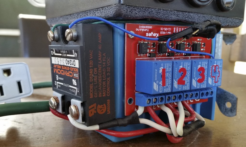
4-Channel, 10-Amp relay module Crydom 40-amp solid state relay DHT22 temperature/humidity sensor
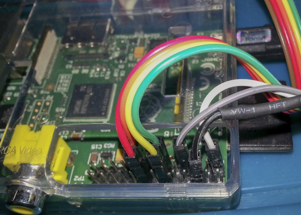
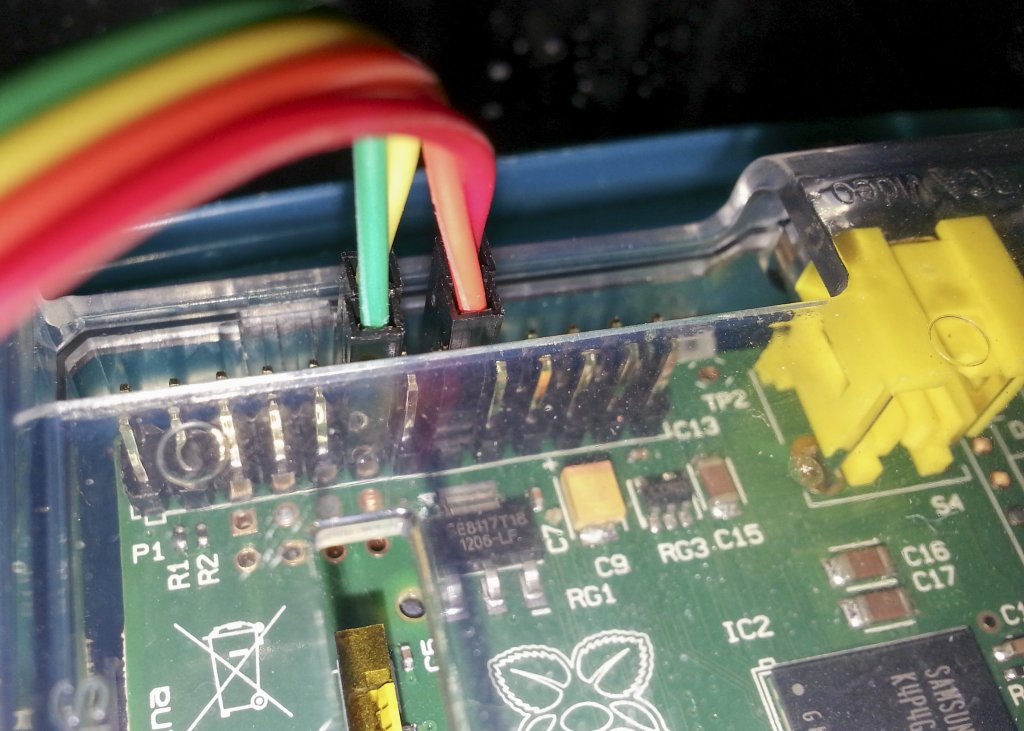
The hardware setup was straightforward. The GPIOs of the Raspberry Pi were connected to relays and each device (heater, humidifier, etc.) was wired to a relay (view the README.txt on Github for specifics, link below).
Remember to always use caution when working around electricity and to always de-energize all components before working on them. Some of the devices described below can be dangerous if not handled or constructed properly. Ensure the control box is not exposed to moisture and that all electrical devices that will be exposed to moisture inside the chamber are either sealed or are capable of safely operating in a high-humid environment. Never exceed the current-carrying capacity of your wires or the maximum rated current of other in-line devices (e.g. outlets, connectors, fuses, etc.). Furthermore, many fungi can be harmful to your health. When culturing any microorganism (especially large biomass), it is advised to periodically perform diagnostic tests to ensure the culture has not become contaminated. This goes for all parts of the cultivation process (including, but not limited to, substrate production, inoculation, fruiting, and disposal). It should also go without saying that one should never consume mycelia or mushrooms of a species that is unknown.
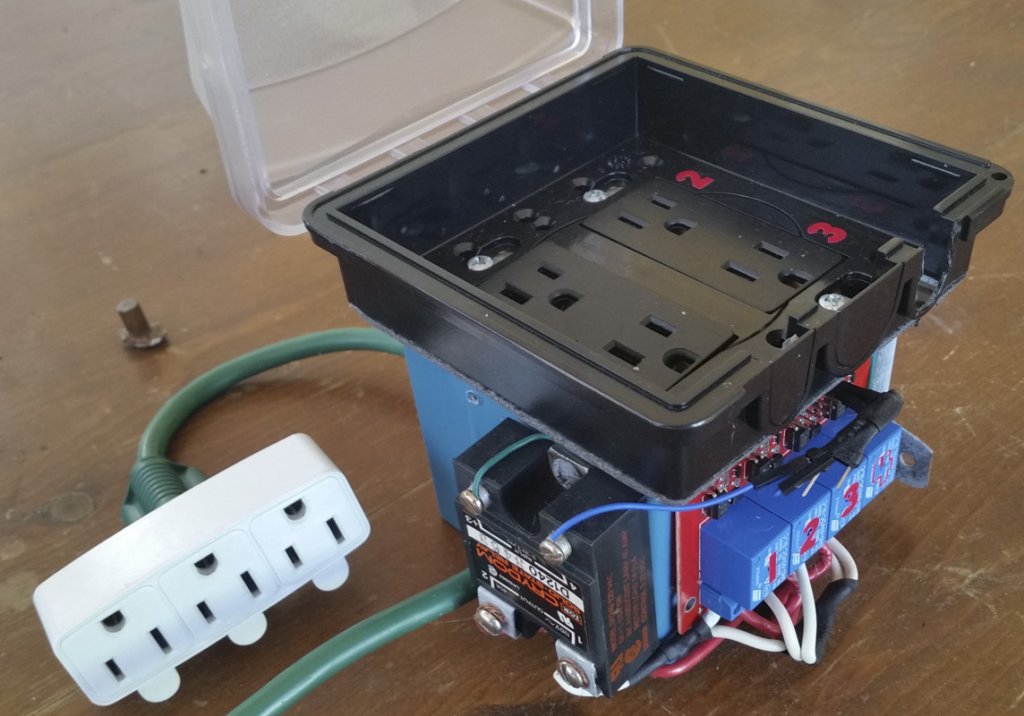
The power control box was constructed with four 120-volt outlets. Each relay controls the main positive voltage to each outlet and the main ground is connected straight to each outlet. One outlet (green power cord in photo) is connected directly to power and is always on. Each relay on the 4-relay board is rated at 10 amps. The Crydom D1240 solid state relay is rated to 40 Amps, and is controlled by the number 4 relay from the 4-relay board. This allows a higher load to be connected to outlet 4, such as a space heater that may exceed 10 Amps.


Programming
The majority of the software relies on two programs, written in C. A logging program reads the temperature and humidity sensors and writes the time-stamped values to log files. A controller program reads from a configuration file and, through PID programming, modulates a set of relays connected to devices (heater, humidifier, circulatory fan, and exhaust fan) until the humidity and temperature in the chamber reaches the values set in the configuration file. cron ensures both the programs run at appropriate intervals.
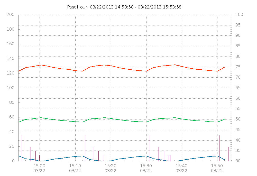
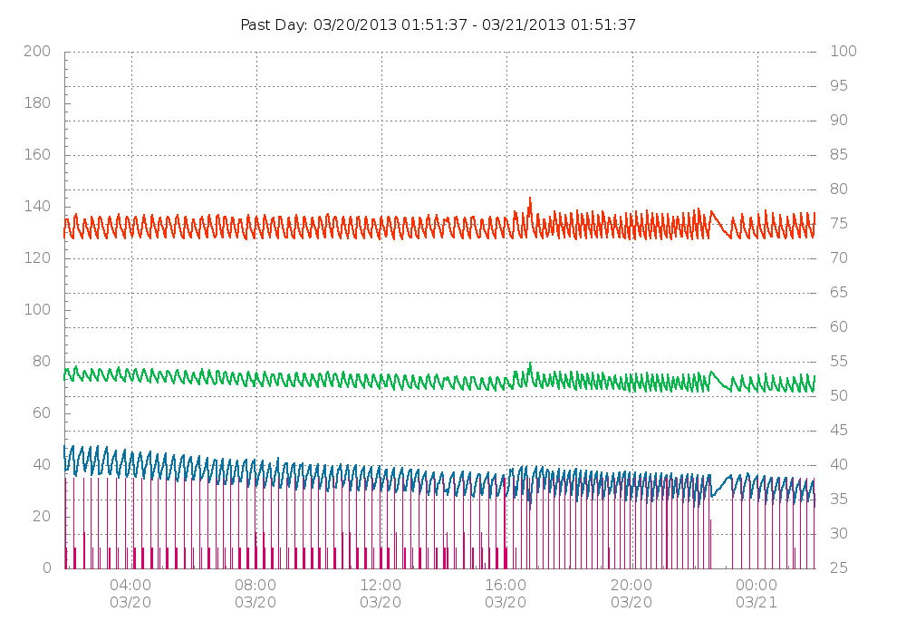
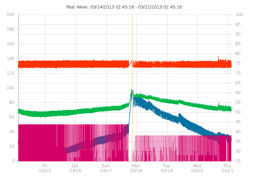
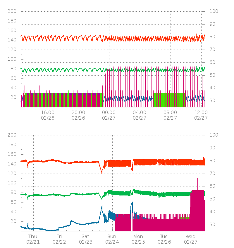
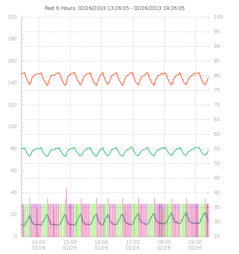
A user interface (HTML, PHP, and Python) was developed for comprehensive viewing of sensor data as well as easy altering of the configuration variables. This was hosted on a Nginx server set up with SSL and an authentication script (PHP) for verifying login credentials. The main page parses and pipes the time and sensor data to GNUPlot to generate several graphs that display (1) temperature, (2) humidity, (3) dew point, and (4) when and how long each relay has ran for, for the past several minutes, hours, days, weeks, months, or years. The user can view historical data on the fly by generating graphs with custom beginning and end dates and can modify the configuration through the web interface.
Web Interface
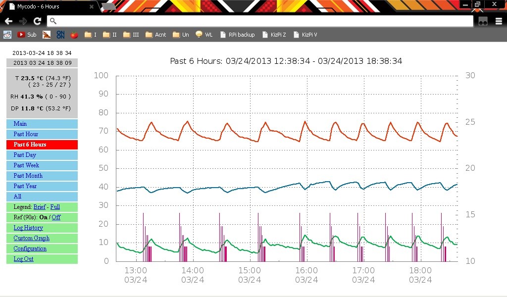
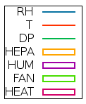
Generated Graphs


Graphs for Mobile

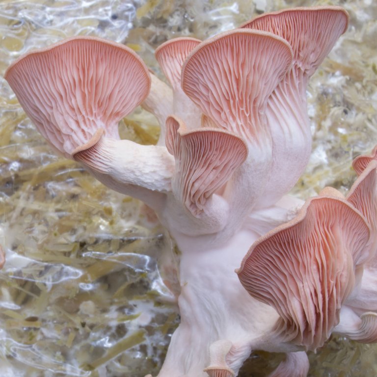
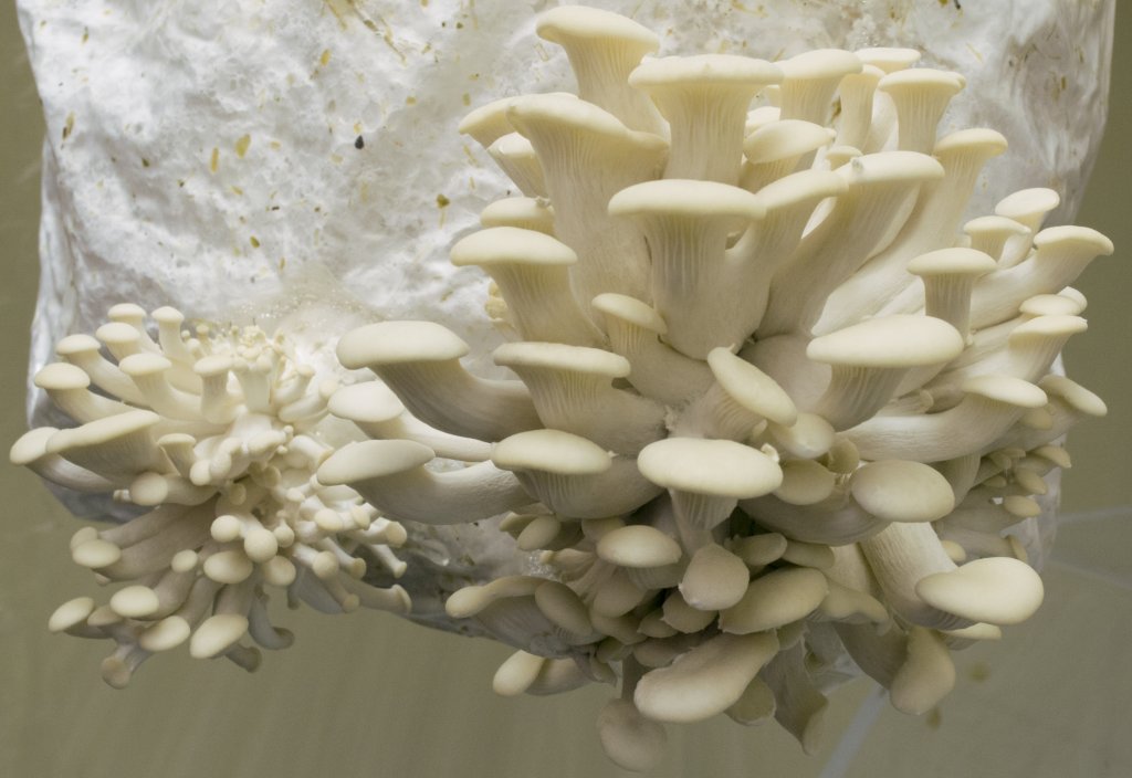
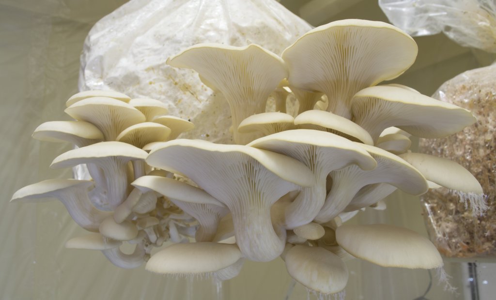
The Fruits of My Labor (white and pink oyster mushrooms)
The middle photos of the large clusters of white oysters grew extremely well and yielded a few pounds in total. The mycelial colonization of the pink oysters had been accidentally heat-shocked early in development and consequently did not fully colonize the substrate (you can see uncolonized hay in the bag in the background), and is likely to be responsible for the smaller yield.
Affiliate links
I participant in the Amazon Services LLC Associates Program, an affiliate advertising program designed to provide a means for sites to earn advertising fees by advertising and linking to Amazon.com, and I make a commission for sales made through affiliate links posted on this website.
Hi, I enjoyed reading your outline of mushroom automation and looking to do the same. Can I ask what sensors are you using to read temp and humidity levels?
Good work and thanks for sharing.
For this build I used the DHT22. I’ve used the HS1101 humidity sensor on a board designed by the late Peter Anderson. However, these capacitive sensors are prone to condensation causing abnormal readings when humidity is very high. I have been looking into thermal conductivity humidity sensors, as these heat up (commonly 200C) and are not negatively affected by high humidity. I’ll document my endeavor if I decide to get this sensor.
Hi Kyle
What humidity sensors you’ve used instead of DHT22 due to condensation problems in a very high level of humidity?
I found the DHT22s to work well at high humidity, so long as your temperature doesn’t fall below the dew point. If you keep the temperature above the dew point, you’re much less likely to have condensation form on the sensor. You can also reduce the likelihood of this happening by encasing the sensor in a protective layer of porous material (such as the AM2315 has) or hydrophobic cotton or other material. This has a greater effect on preventing small particulates from landing on the sensor surface, which I believe will affect accuracy more than condensation (which will eventually evaporate). Also, the quality of the water and method you’re using to raise the humidity could affect the accuracy. For instance, if using a method that relies on creating an aerosol and the water quality is low, this could leave residues wherever the aerosol droplets land. Although I’ve been able to drastically extend the life of DHT22s by creating these protective enclosures, I would still recommend having backup sensors handy, to replace if you see accuracy diminishing. I would typically get a year or two use out of them, but that will vary depending on the amount of use, type of enclosure, water purity, and method used to raise the humidity.
What if you wanted to add more sensors such as multiple zones for your humidity and temperature or even soil moisture sensors in some of the plants? Would the software allow this? I also would like to add drip irrigation to mine with small valves controlled by servos or even the relays. Can I ask how you would go about expanding this on the software side if you wanted to do the same? The software looks incredible!
You could certainly add additional sensors. You would have to program the Pi to interpret the signal from the sensor, then decide what to do with the data (what relay(s) to activate/deactivate). With the framework I have on Github, it wouldn’t be difficult to expand the number of sensors and outputs. As for an irrigation drip, there are a number of ways to get your desired result. I would be inclined to use a water pump (to pump water up to a holding tank that has drip tubing) or a solenoid valve instead of a servo. This would utilize the relays already in the system. What I was going for with the relay cluster was a simple design that could be easily expanded to a number of different uses. I’m currently working on a project that’s an expansion to this system, with 8 relay-switched outlets. There should be a sizable update to the control code and web interface.
Hey Kyle,
This is great. I have been looking for something like this on a Raspberry Pi to adapt for my terrarium. Thanks a bunch for instructions and sharing your code.
I appreciate this documentation. What humidifier are you using?
The first system I built used an ultrasonic fogger in a sealed container of water and an air pump connected to pump the humid air into the chamber. Both the fogger and air pump were activated at the same time. The latest system uses a common household humidifier that can be bought from most department stores and an improvised fitting to connect it to the chamber.
Hey kyle, just wondering whoch gave you better performance, the ultrasonic mister or the store humidifier?
They actually use the same technology, but the consumer version incorporates a few things that make it easier and safer to use:
1. A float sensor that prevents the ultrasonic mister from turning on when the water level is too low.
2. A large reservoir that will fill a smaller reservoir when the smaller reservoir gets too empty (there needs to be a precise thickness of water over the ultrasonic mister for it to operate efficiently).
3. A fan that will push out the humid air that’s created in the humidity chamber.
In order for you to effectively use just an ultrasonic mister, you will need to hook up some sort of pump (I’ve used an aquarium pump) to force the humid air out of your holding chamber. Then you will have to worry about how you will detect when the water is getting low, so you don’t run it while dry. Then you can figure out a water refill system that will allow you to fill a larger reservoir that will keep the smaller humidification chamber at the same water level (rather than hand-filling very often you can just fill the larger chamber less often, or automate the filling).
Of course there are other variations, but I thought I would mention how to mimic the consumer version because it is an effective design.
Now, if you require a large amount of humidity, then perhaps multiple ultrasonic humidifiers and a custom water filling system could be the more economical and cost-effective route.
Very nice I want to start a musroom farm
They sell inexpensive prewired humidity/temp controllers for about 45$. Im setting up my first F.C and am using one with a cool mist humidifier. Also 2 industrial air pumps eatch meant to run 12 air diffusers. The air passes through several layers of hepa filter and there are many small holes drilled on the other end of the container for fae as the air going in is so great amd creates a very strong positive air pressure.
Nice to improved my knowledge and highly useful tips for my mushroom farm. Thank u.
Hi Im considering making your mushroom cultivator. May i know the hardware needed for it to work? Im just new in to rpi automation. What i need are the temp and humidty sensors right? Can i use dht 11? For the relay board, what can i use as an alternative since it is not available in my country. And how many do i need. For the solid state relay as well what can i use and how many. Thanms
Hi Gian,
You’ll need at a minimum: a humidifier, a heater/AC to regulate temperature, a fan for exhaust. For each of these, you’ll need a way to control it. Heater/AC systems can typically regulate themselves unless you want more control, which you then can use Mycodo for if you desire. The humidifier and exhaust fan require 1 relay each to have Mycodo operate them. Solid state relay boards are common on Bangood, ebay, Amazon, and many other stores around the world. You can also by from Mouser.com or DigiKey.com. I would not recommend the DHT11, due to its unreliability. There are a number of other temperature/humidity sensors supported by Mycodo that you can see the most up-to-date list in the manual (https://github.com/kizniche/Mycodo/blob/master/mycodo-manual.rst#input-devices).
Do you know what changes would need to be made to make this work for a UK electrical system?
You would merely have to use a power supply that is able to accept 220 VAC as the input voltage as well as select relays that are compatible with this voltage. Digikey and Mouser have a good filter system for finding parts that meet these specifications. Alternatively, sites Like Amazon, Bangood, and the like are a good resource for electrical components. If you have any question about specific parts, I’ll try to help, but without more detail, I’m limited with what I can recommend.
Cheers,
Kyle
Thanks dude. I try figure it out. Good to know that it’s not much different from what you’ve crafted for the US power supplies
Sorry. back!! :) I’m trying to put together an equipment list so far I’m looking at the below.
https://www.ebay.co.uk/itm/4-Channel-Relay-Board-Module-Opto-isolated-for-Raspberry-Pi-PIC-ARM-Arduino/143208234799?hash=item2157e03f2f:g:9U0AAOSwxa9axKvt
https://www.mouser.co.uk/ProductDetail/Omron-Automation-and-Safety/G3FD-102SN-AC200-220?qs=zHLA69qKNxCZ0rgbDS%2FrWA%3D%3D
I can’t find a power box and I wonder if it goes by a different name in the UK. Would it be a transformer? (ha)
Also what cables will I need?
I’ve never built a Pi or any electrical device before. Sorry about all the very specific detailed questions.
If you’re inexperienced with circuit design, I would suggest going with the pre-made relay modules, like the first you linked. However, if the devices you would like to control draw less than 2 Amps, I would suggest going with a solid state relay module, such as those made by Sainsmart (https://www.amazon.com/gp/product/B00ZZW7MI6). These will have a longer lifespan, be more reliable, and be silent, compared to mechanical relays. The mechanical relays you linked to are rated up to 10 Amps each, and are not a bad product, but once you go to solid state relays from mechanical relays, you may never go back. When I need higher power-switching capabilities, I often use Crydom solid state relays, which come in panel-mount (http://www.crydom.com/en/products/panel-mount/) and DIN rail-mount (http://www.crydom.com/en/products/din-rail-mount/) options, and can be found on both Digikey and Mouser.
For power, I typically just use the recommended power adapter for the Pi, unless I’m powering anything more than the Pi (such as sensors or other 5-volt devices). This standard wall-type plug can be plugged into one of these power receptacles (https://www.digikey.com/short/pr4hz0 Digikey part Q228-ND). This is then connected to your main AC lines by quick connect connectors (https://www.digikey.com/short/pr4hmr Digikey part A114078-ND). The version of the receptacle, above, is the US version, but you would need the Type G version if you go this route (I’ve had a difficult time finding the UK, Type G, part, otherwise I would link to one).
Alternatively, for power, if you go with something like a DIN-mounted power supply, you won’t need any plugs (https://www.digikey.com/short/pr4bt7 Digikey part 1145-1233-ND). DIN rails (https://www.digikey.com/products/en?t=580&pv352=2162) are convenient, and there are even DIN Pi mounts that make building an enclosure an easy process.