
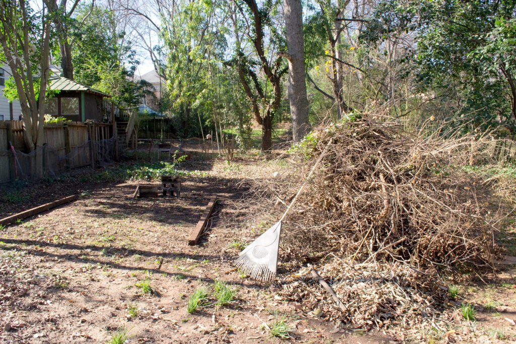
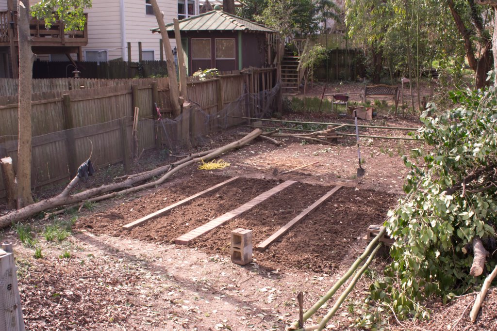
I found the highest and brightest part of my yard, cleared the vegetation, lightly tilled the earth, and laid bricks and 4x4s to walk on. I erected a fence from bamboo harvested in the yard, to protect it from an American bulldog that shares the yard.

Although the box I chose to house the circuitry in is waterproof, space constraints and my desire to control and monitor from within my house influenced the design heavily. I also wanted this project to be modular, so if I wanted to change the sensors and power other devices, I could easily do so.
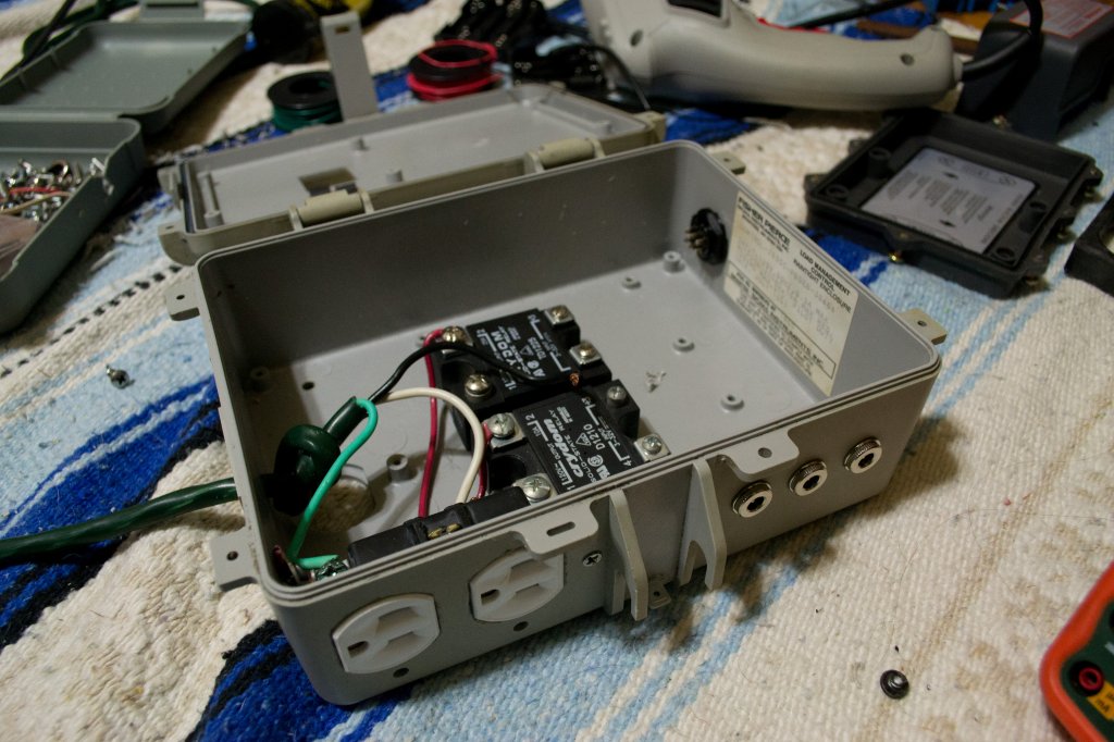
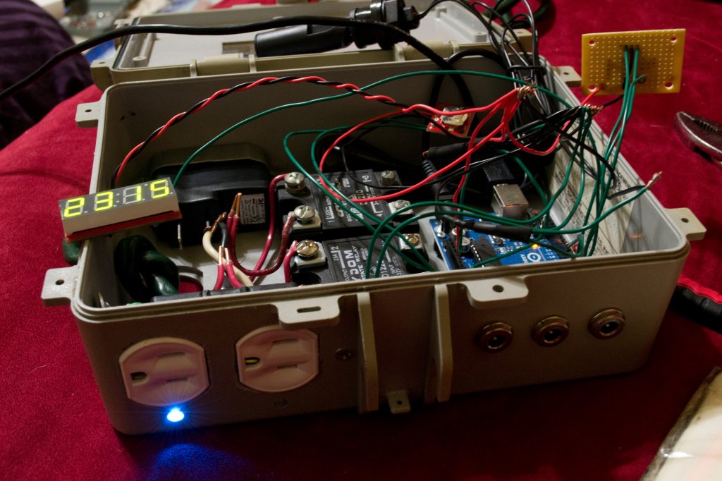
The design I ended up with was comprised of three barrel plugs and a single 3-lead audio plug (float sensor, pump pressure switch sensor, temperature sensor, and rain sensor), two solid state relay-controlled electrical outlets (well pump and solenoid valve), and a blue LED next to each outlet as a power indicator.
The 1/2 HP well pump is rated output is 9 gallons per minute (GPM) @ 30 or 55 pounds per square inch (PSI), and has a current rating of 8.5 amps. At 120 volts, that’s 1020 watts of power consumption. If we assume these figures are accurate, we can take Atlanta’s January, 2012 electricity cost of $0.113/kWh (killoWatt-hour) and project how much it would cost to water every day of an 8-month growing season, for 30 seconds.
(30 seconds/day) x (30 days/month) x (8 months/year) x (1 minute/60 seconds) x (1 hour/60 minutes) = 2 hours.
(2 hours run time) x (1020 Watts) = 2040 Watt-hours = 2.04 kWh.
(2.04 kWh) x ($0.113/kWh) = $0.226
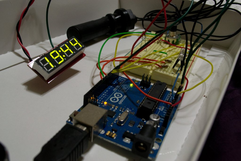


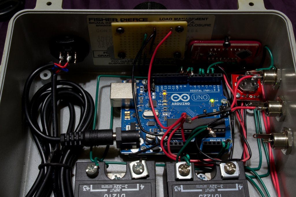
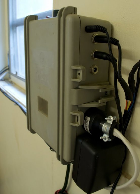
Control Box
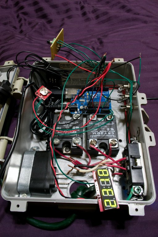
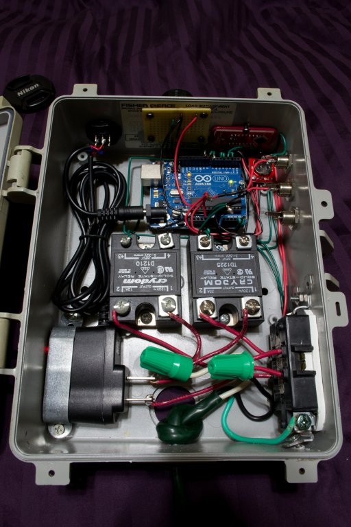
The electrical components include an ATMega328, two Crydom D1210 solid state relays, 7-segment display, reed switch float sensor, 24-volt solenoid valve (sprinkler valve), real time clock module, temperature sensor (10k thermistor), two blue LEDs, push-button rotary encoder, and a 5-volt USB power adapter.
The ATMega uses the relays to control the power to the well pump and solenoid valve connected to the house’s water supply. A schedule is set with the rotary encoder and the real time clock is referenced to turn the well pump on at the scheduled time. If the rain barrels begin to run low on water, the float sensor will signal for the solenoid valve to be opened at the house’s spigot to begin filling a barrel with water. This prevents the water level from falling below the pump’s intake pipe and allowing the pump to run dry, seizing or destroying the pump in the process. The temperature sensor signals if the temperature is too low and prevents the pump and valve from operating. The rain sensor prevents watering during or following a rainfall.

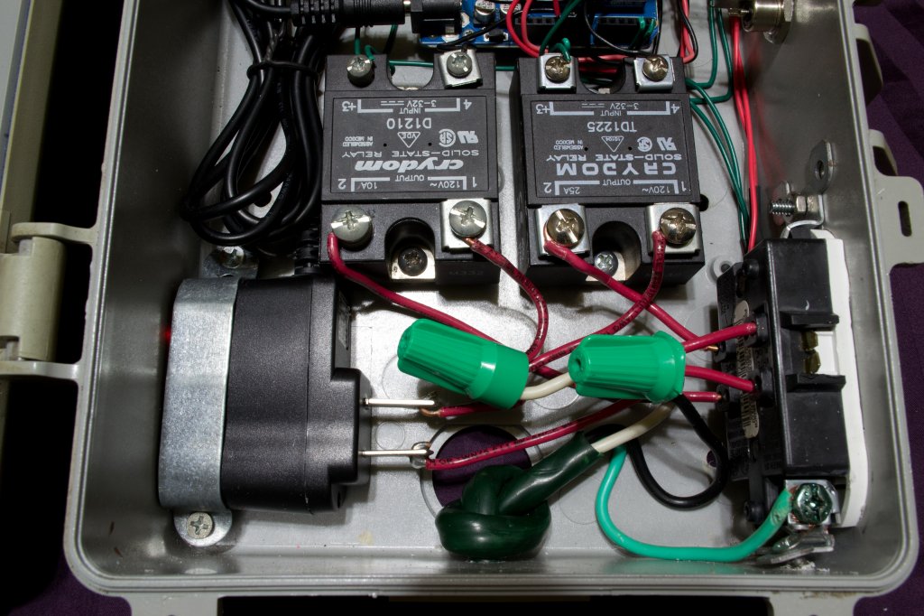

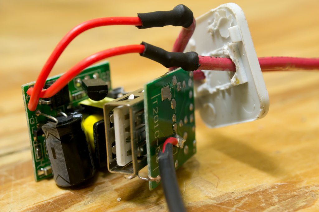
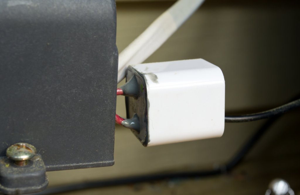
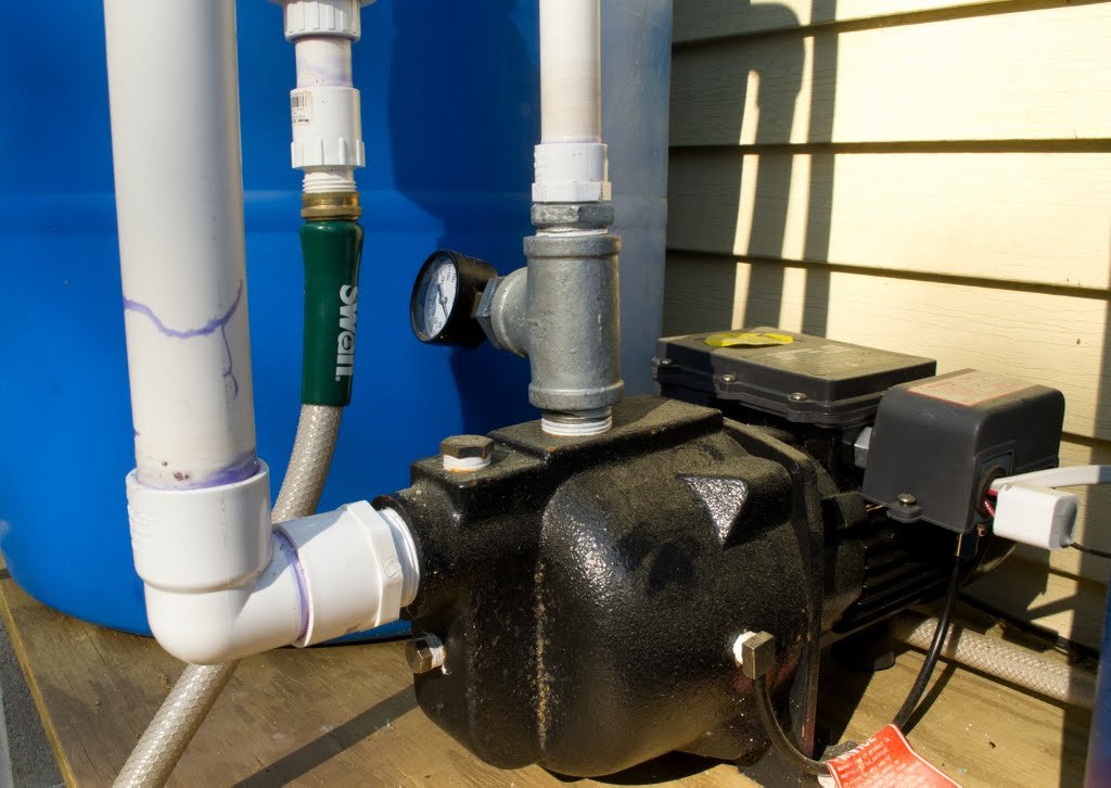
While powered, the stock well pump relies on a pressure switch to enable and disable the current to the motor. A situation where there may be a blockage in the outflow line would cause pressure to build up. If the pressure measured in the pump head exceeds ~50 PSI, the switch will interrupt the power to the pump to prevent damage. Because no pressure tank is installed, the line pressure quickly drops after the power loss, restoring power to the pump. This off/on cycling rapidly occurs, about 2 to 3 times per second, and if the line pressure doesn’t return to normal, the pump could eventually burn out. To prevent this, a 5.5v USB power adapter was utilized for a solution. This acts as a signal from the pressure switch that power is being given to the pump. When this 5.5v signal is lost when the pump relay is energized, the whole system is programmed to shut down, as it indicates the pressure switch has been activated.
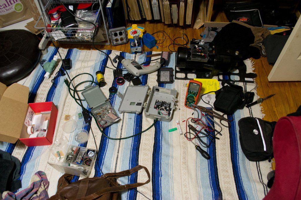
The enclosure was opened and wires were soldered to the AC input and DC output leads. The enclosure was resealed with marine epoxy. While testing, it was discovered that the capacitor within the USB adapter prevented the voltage from dropping enough within the amount of time the pressure switch stayed off in it’s on/off cycling (250-500 ms). This was resolved by adding resistors to drain the excess energy in the capacitor. I was able to reliably detect a drop in voltage after adding resistors in parallel reached roughly 30 Ohms.
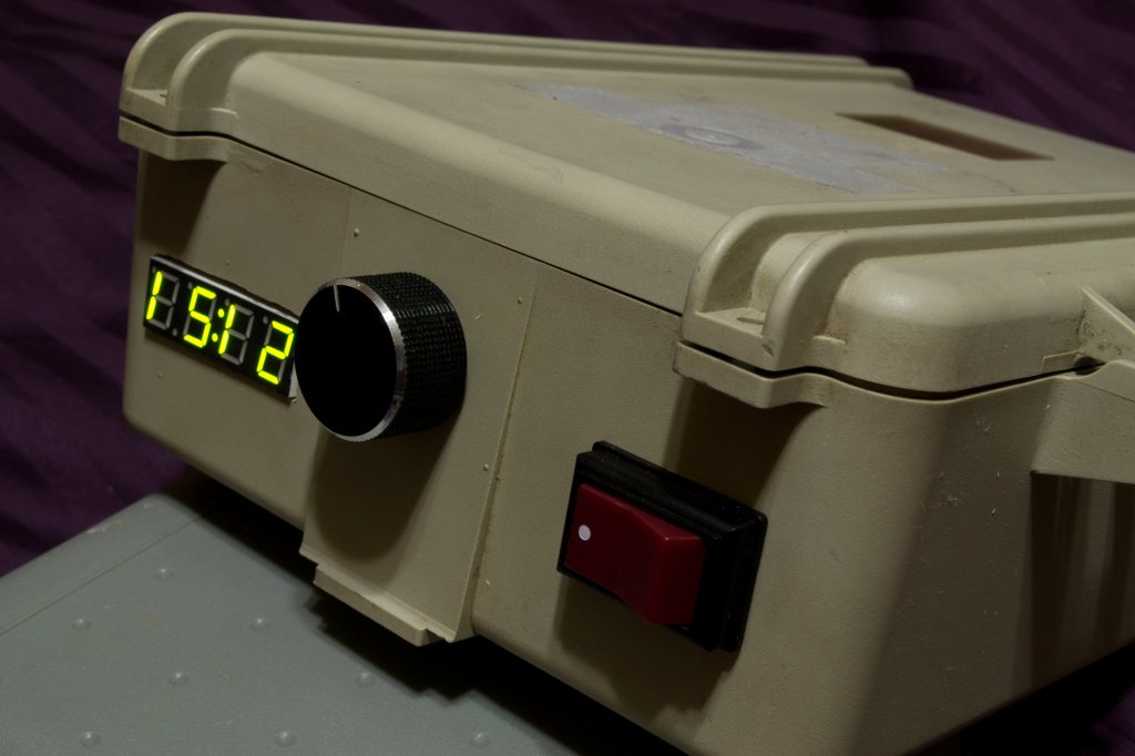
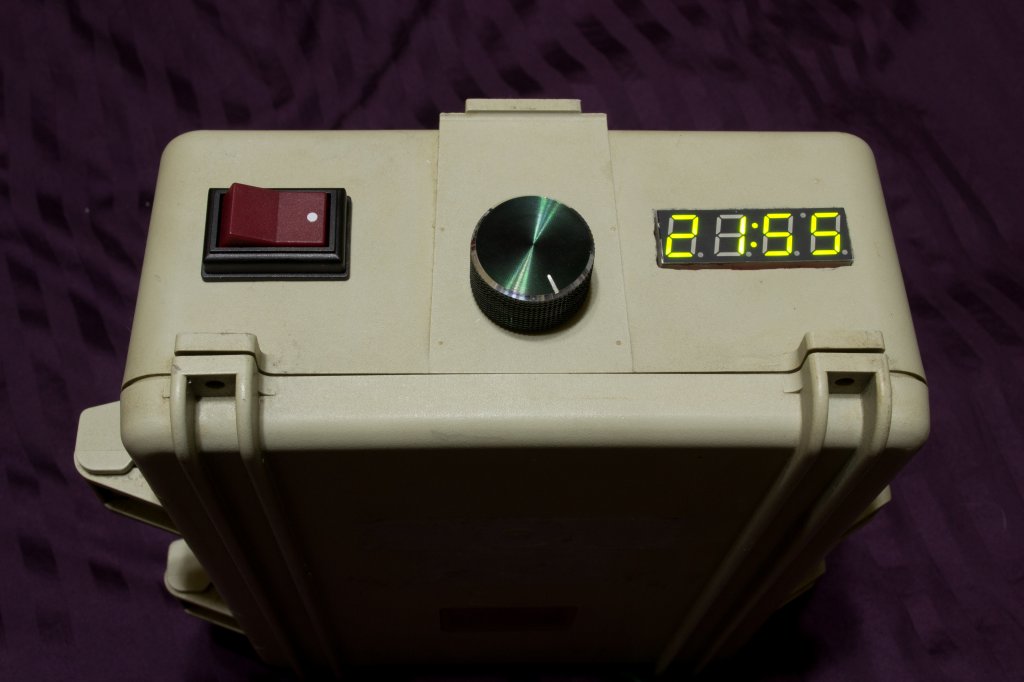
Operating Instructions
 -*-*-*-*-* Operation and Navigation -*-*-*-*-*
 The current time & temperature will alternate on the display by default.
 If the colon is blinking when the time is displayed, the schedule is on.
 If the colon is not blinking and stays solid, the schedule is turned off.
 While the time & temperature is being displayed. The knob can be pressed
 to activate the control menu. Turn the knob to change a value, then press
 to confirm the value.

 -*-*-*-*-* Menu Options -*-*-*-*-*
 1: Exit the control menu and return to displaying the current time.
  2: Display schedule(s) in the format: start time, duration on, days
 between running, next run day (1=Mon…7=Sun).
  3: Change schedule
  A: "#  x" #: Which schedule, x: How many schedules to use (up to 3).
  B: "XXYY" X: Starting hour, Y: Starting minute. Selecting the time will
     confirm & display the next schedule time.
  C: "#  x" #: Which schedule, x: watering duration in seconds (~5
     gallons/minute).
  D: "#d x" #: Which schedule, x: how many days between running the
     schedule.
  E: "#n x" #: Which schedule, x: Which day of the week to start schedule
     (1=Mon…7=Sun).
  4: Override the pump (to run the sprinkler) to either remain OFF or ON
  5: Override the valve (to fill the barrels) to either remain OFF or ON
  6: Turn the timer schedule OFF or ON
  7: Reset the pump and valve overrides so they return to a scheduled
     operation (if schedule is turned on)
  8: Display temperature history over the past 24 hours, 0 is the most
     current temperature stored

 -*-*-*-*-* Emergency Modes -*-*-*-*-*
 If an emergency is detected, the valve and pump will remain off until the
 button is pressed to resume normal operation. During emergency mode, one of
 the following will interupt anything currently being displayed:

 -E-1: The valve was open > 15 continuous seconds. This indicates the water
 is not activating the float switch in a timely manner. Ensure the hose going
 into the tank is connected & clear, the valve is operational, the spigot is
 open, the tanks are free of leaks, the float switch is free to move, and the
 switch is indeed activated when the water level reaches the sensor.

 -E-2: The pressure switch began rapidly turning on and off or the pump has
 run dry. This indicates there is too much pressure building in the pump outlet
 or no water at the pump inlet. Ensure the outflow hose from the pump is not
 kinked, the sprinkler screen/heads are clean, and there is an adequate amount
 of water reaching the pump inlet.

 -E-3: The float switch has been activated after more than 3 minutes from when
 the end of a scheduled watering. This indicates there may be a leak or water
 is being manually removed via the barrel's spigot. If the barrels were allowed
 to fill, which could take over a minute of the valve turning on and off [to
 equilibriate the water levels], the float switch should not activate this late.
 If water is being manually taken out, remember to exit emergency mode in order
 to resume the schedule.
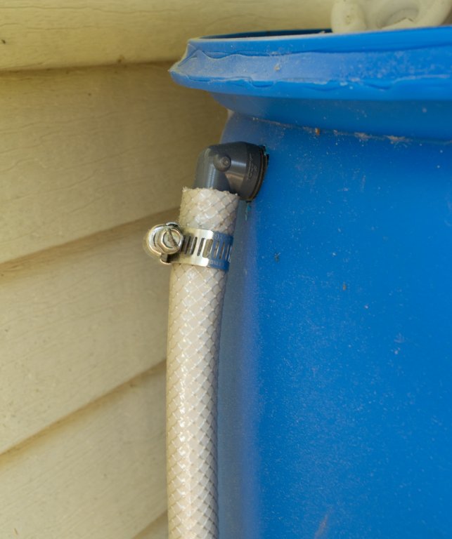
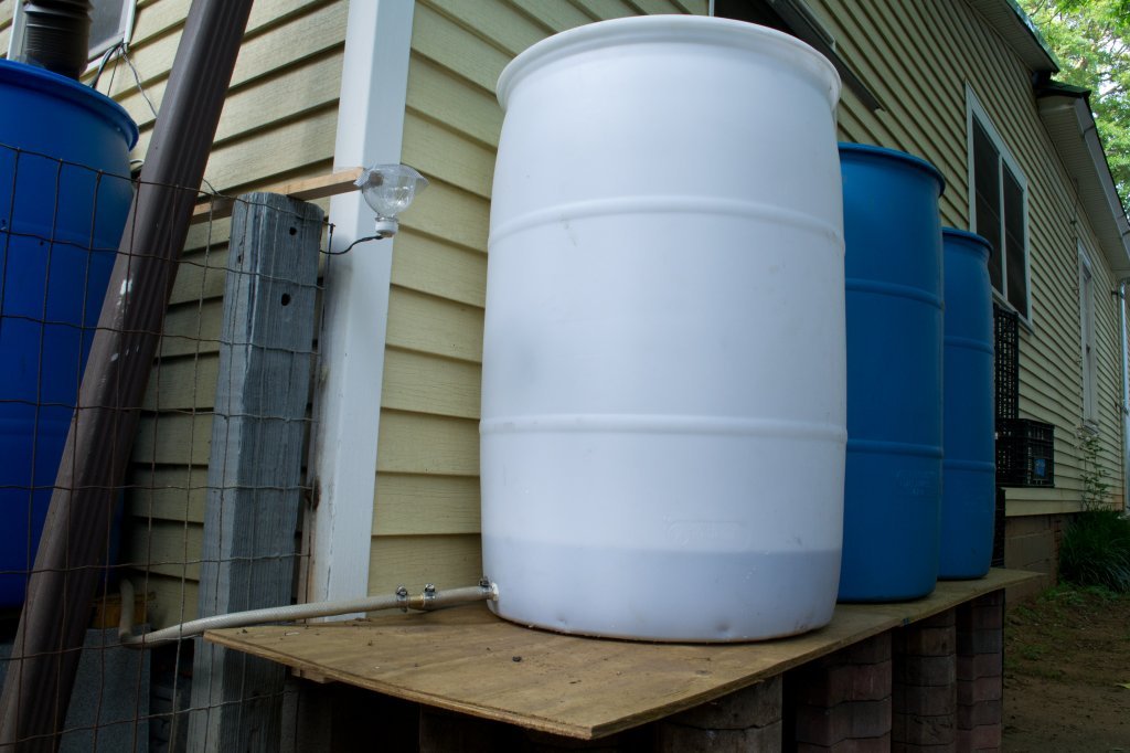
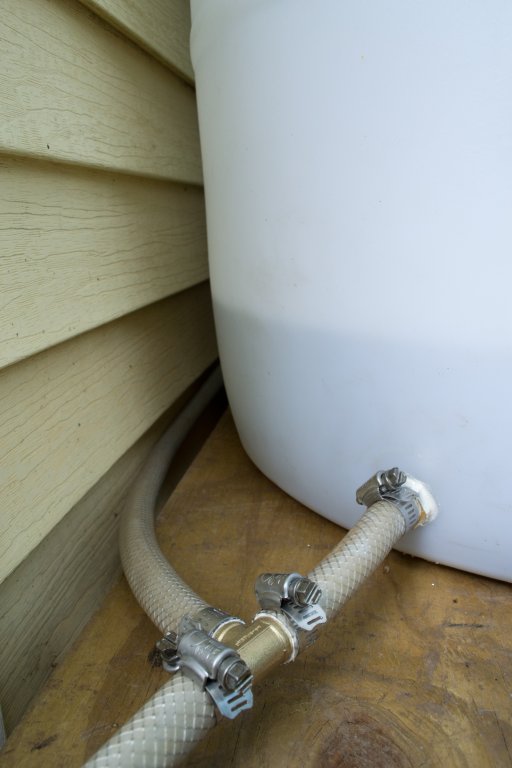
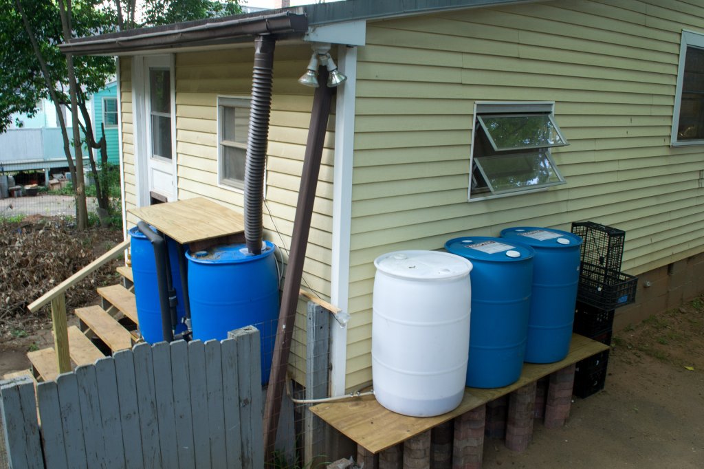
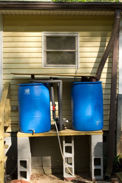
Water Storage and Delivery System
Water enters one 55-gallon barrel by flex tubing from the gutter while hoses connecting all 5 barrels equilibrates the water throughout. The pump siphons from one barrel and pumps it through a garden hose that runs out to the garden.
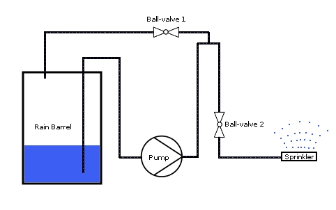
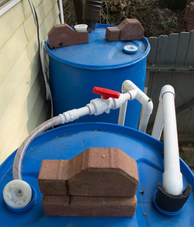
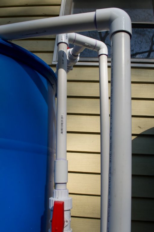
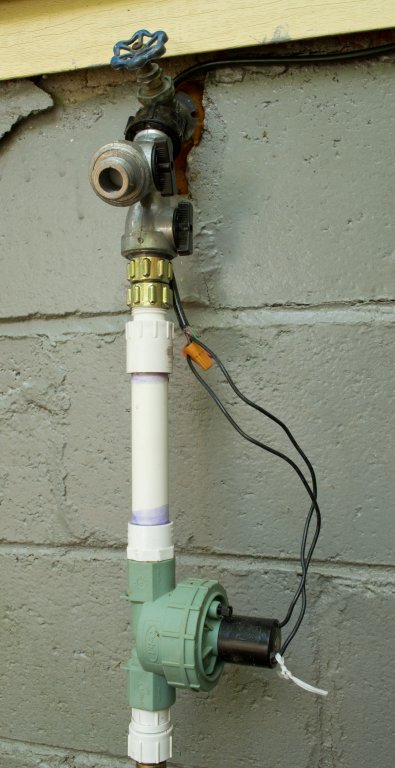
The outflow pipe from the pump rises higher than the highest possible water line, to prevent water from siphoning out while the pump is not running. This is only possible when a separate pipe extends from the top of the bend to allow air to be introduced into this bend immediately following the pump being turned off. This vent serves two purposes- it allows air to flow into the top portion of the pipe when the pump shuts off, preventing the gravitational flow of water toward the sprinkler from drawing all water out from the barrels, and it also alters the water pressure that’s allowed to reach the sprinkler by either closing (increase pressure) or opening (decrease pressure) the Ball-valve 1 (see diagram below), diverting the flow back into the barrel so no water is lost. With Ball-valve 2 in-line after the bend, there is now the ability to completely alter the pressure from 0% to ~100% beyond Ball-valve 2.
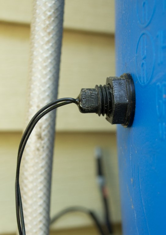
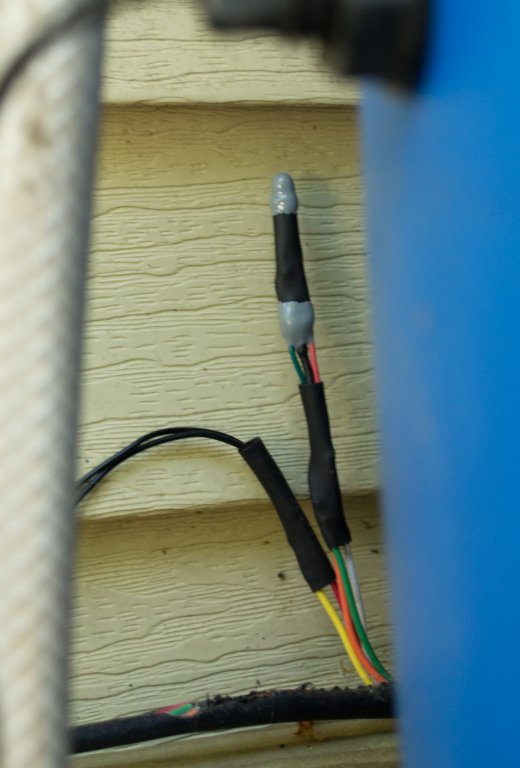
The float sensor is inserted through a drilled hole in the barrel and tightened for a water-tight seal. The 10K thermistor and 10K resistor were encased in heat-shrink tubing and epoxy for water resistance.
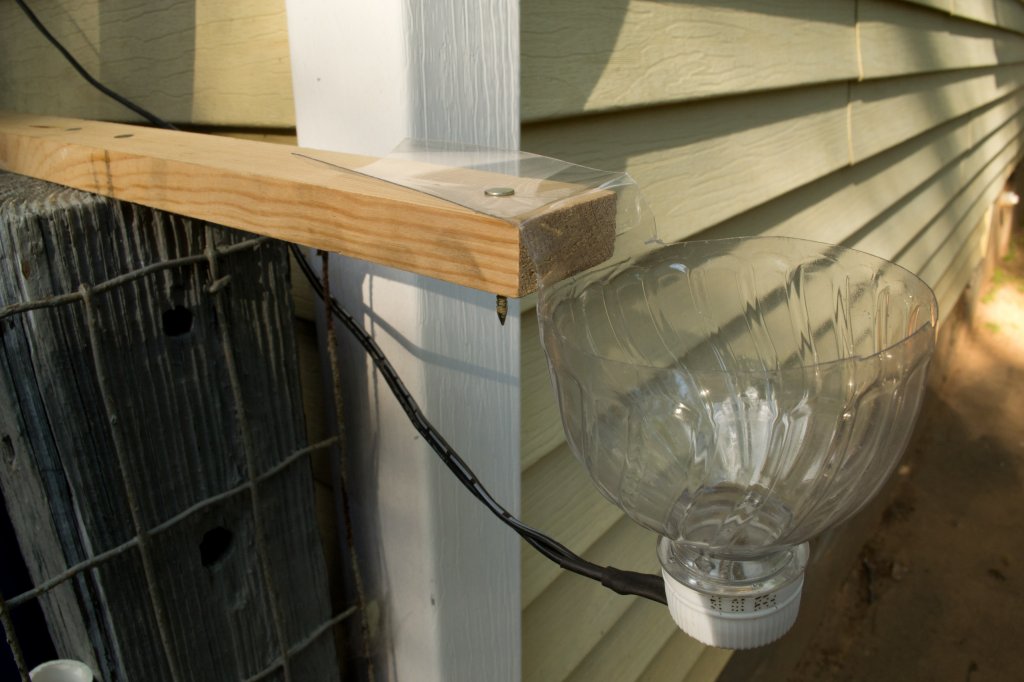
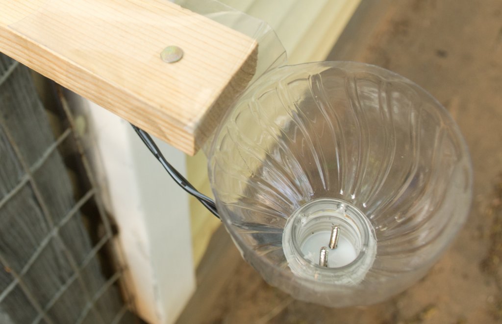
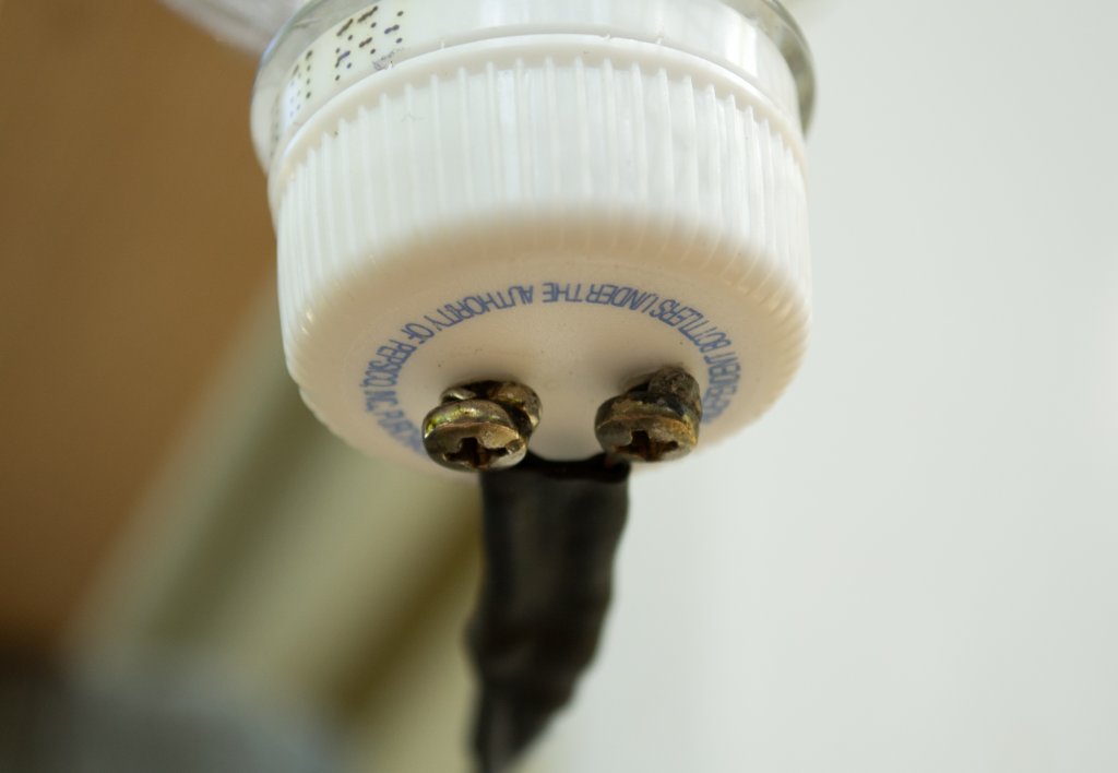
Rain Sensor
The principle behind how this works is conduction. When there is no water in the cup, air separates the two screws. A wire connected to one screw carrying a 5-volt potential and the other screw is wired to an ADC pin of the ATMega. Since this large air gap is non-conductive, these 5 volts are not detectable by the ATMega. When rainwater fills the cap, it acts as a conductor, allowing electrons to pass from one wire to the other, completing the circuit and signaling to postpone irrigating the garden.

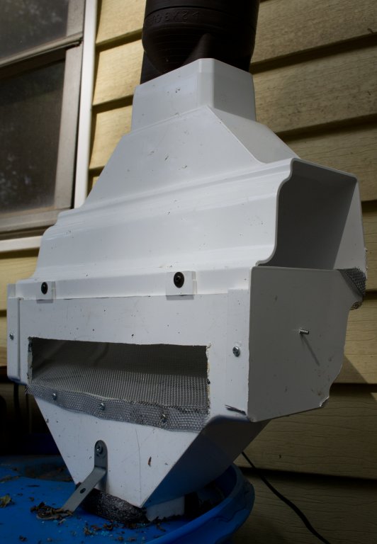
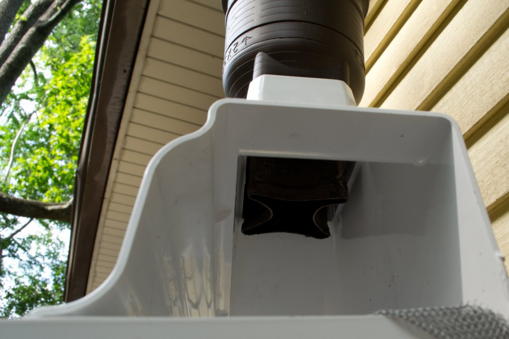
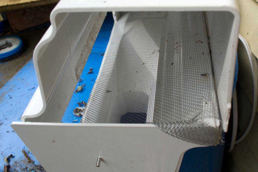
Water Collection Filter
To prevent large debris from entering the barrels, a self-cleaning filter was made from two symmetrical gutter spouts connected together and a metal screen mounted inside at a 45-degree angle from the entry port. Debris that enters is pushed by the water to exit the filter.
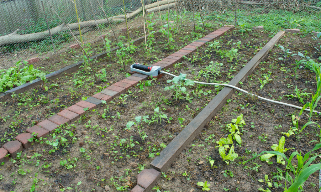
Finally, a photo of my current garden using this system, at the beginning of the growing season. I hope this has served as entertainment, inspiration, or a practical how-to for your own garden project.
wow nice :) i like it !
Great pictures, awesome project
Awesome, I love the walwart mounting. Did you see my WarmDirt project? http://www.spudcentral.com/potd/120318.html
Thanks. I’ll have to look at it more carefully later, thanks for the link.
The next thing I’d add – a rain gauge, so that if you’ve got enough water from rain over the last n hours you don’t turn the irrigation on.
(Got here from http://hackaday.com/2012/03/29/rain-barrel-irrigation-system-keeps-your-plants-fed-when-youre-too-busy/ by the way)
It is documented in the build, but that’s what the fourth unused barrel-plug will be used for.
I am interested in your pressure control system – can you post a schematic about the vale the water divergence back into the barrel as a means to control pressure with constant pump output. I have seen PWM pump control solutions with heavy industrial triac but at 9Amps I prefer the constant speed approach – just like in aviation the constant speed prop has proven superior any time there are engines involved…
I’ve amended the build information to include a schematic and explanation of my simple yet elegant pressure control system. The past few months I’ve been exploring the options of motor controllers and such, then one day this solution hit me.
Beautiful! Thanks. Boy and I was suspecting some super duper tri-pipe ball valve that redirects flow on a 90 degree scale of rotation… LOL Great solution. Thank you.
Awesome project man, but why the messy arduino job, just adding a wingshield would lower the chance of wandering wires significantly http://www.sparkfun.com/products/9729
I’ve made my own shields in the past for ease and security of wiring, but I found that in enclosures like this that are completely sealed without the possibility of wires being pulled or shaken (the whole box is screwed to the wall), everything stays fairly well-put. The 180-degree bend that some of the wires have before going into the arduino, along with their contoured shape that runs along the back of the box, makes them rather secure as well. Also, I needed to cut the cost somewhere, so I tried to do all this with the necessities.
I’ve used shields(nice ones that i’ve received as gifts)… but I ultimately end up soldering to pin strips and making wiring harnesses for my applications. They aren’t worth the spend, for something that is finishe and doesn’t need frequent tweaking. I’m nearly complete with a similar project. I’ll return here and give you a link when I’ve put a write up on my own site. Check out the DHT11 Moisture sensor if you aren’t already aware of them, they are super cheap, compact, and really useful. Also, I’ve made mine wireless with an APC220(costs less than a good shield), so it can be monitored within a few hundred meter range of the units location. Mine is attached to a linux machine, and I can SSH to the machine make changes, as well as monitor remotely. And I added a backup battery for power failure, as not to through off the timer library, and change the lighting schedules. Great post. I’m glad to see more DIY garden automation to such a a degree. Cheers.
Very nice!
Very good project.
You inspired me for doing something similar…
Thank you!
Are you a Greek?
Nicely done. But I’d make one slight change to it, I think I’d drill two tiny holes (1 – 2mm) in the bottom of the rain sensor. Just big enough so that with the rain stopped the sensor drains in a few minutes.
There are two holes in the neck that are barely discernible in the photos. This allowed only the cap to fill with water. I wanted a design that would keep the rain sensor tripped for a day or two, depending on how much rain had been received, so I needed to get the correct level of water that evaporation would remove after that time. I eventually modified the hole placement to retain just a few millimeters of water in the cap. I found that this can evaporate in about a day, depending on the humidity, temperature, and sun intensity.
Thanks for posting this – I am about to get started on my own Arduino rain barrel project. I particularly like your Filtration system – it looks like it is somewhat self cleaning.
I am curious as to why you time your water schedule. I have see other similar applications where they will measure the soil resistance to determine moisture content (measure its resistance..) It seems to me that by going on soil resistance, there would be less water usage.
Again, thanks for the great article, you have lots of great ideas of which I will be using.
— Mike
I went with timers because they are highly configurable and I knew they would reliably work right away. I found the amount of water that I collect is more than enough for the watering schedule I use, so I haven’t had a need to change it. I did plan for future expansion by including an unused input on the outside of the box.
I’m glad you found this useful. If you document your build, come back and share.
Cheers
First off: awesome project!
One component I’m curious about is the float switch. I’ve found a bunch similar on eBay, but either are thread-only or push-fit. Yours seems to look similar to both types.
Where did you get that float switch? Did you have any leakage issues out of the barrel, or did you seal the hole with caulk?
I found the float switch on eBay. It is threaded with a rubber gasket. It must be dropped into the barrel then pulled through the opening before the nut can be put on. I initially had a slight leak, but that was because I had improperly seated the gasket. Once the gasket was in place, it has been water-tight ever since. The barrel is large enough not to produce a substantial curvature that would inhibit sealing, and the gasket is thick and rubber, so it was able to conform to the curvature to make a good seal.
This looks like mine, but I believe the gasket is backwards:
http://www.ebay.com/itm/Horizontal-Water-Level-Sensor-Liquid-Float-Switch-PL-4-/250872028406?pt=LH_DefaultDomain_0&hash=item3a69235cf6
How do you connect to it? I’ve found for a similar application PLCs (Power Line Communication w/ ethernet port) come as a glove for these applications… no need for extra wiring, power it from mains, then hook the RPi or whatever with an ethernet cable.
This project used an ATMega microcontroller. I used barrel plugs for the inputs since I only needed two wires per sensor (float switch, thermistor, conductivity for rainwater, and power response from well pump energizing). The POE is a great idea. I’d be concerned if it was capable of supplying sufficient current if I were to start adding sensors and devices that drew from it.
I didn’t refer to Power Over Ethernet, that would require you to lay an outdoor ethernet cable, but the opossite: two devices that plug directly to mains, and use mains grid to transmit ethernet.
As you are already powering by mains at the garden location, the only thing needed would be getting two PLC devices, “pair” them by plugging both on a power strip, then positioning one at a suitable place at main house and plug its ethernet to your LAN; the other one can be inside the rain project box, wiring it to mains; you’ll have an ethernet port in layer 2 connectivity with main hoyse LAN straight there.
In other words, your mains installation acts as network cabling; as long as both devices are plugged to the same mains ring, you’re done.
These are the devices I refer to:
https://www.amazon.com/7inovaTM7HP120-Ethernet-Powerline-Adapter-Starter/dp/B00P9IYFTU/ref=sr_1_1?ie=UTF8&qid=1511633265&sr=8-1&keywords=PLC+ethernet
Guess the ATMega doesn’t have ethernet capabilities, but when using a RPi or other device supporting networking, using PLC is a bliss, as you have to bring power to the equipment no matter what; that same power wiring will act as ethernet “cable” towards your house.