
With the acquisition of a new distillation unit, I decided to transfer and adapt the Arduino control interface from my previous distillation unit to this one. I wanted a redesign that would reduce size and increase functionality. The 120VAC solid state relays, Arduino, and a resistor were the only components that made the cut into the new design. A 16×2 LDC and a rotary encoder with a push button were picked up for input and feedback. The rotary encoder allows unrestricted rotation as well as having a normally open push button. This, in combination with an LCD, seemed to be the simplest interface with the greatest functionality.
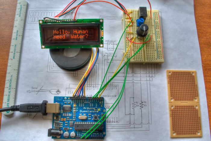
On the breadboard, the blue potentiometer controls the backlight brightness and the black relay switches the backlight on and off. Some of the code from my previous interface could be used, but much of it had to be rewritten for use with a rotary encoder instead of a 6-position dial and an LCD instead of a single LED.
Coding was fairly straight-forward. The LCD was used in 4-bit mode to allow a connection requiring only 6 output pins, and was controlled with the LiquidCrystal library. I could not find an LCD menu library for a rotary encoder, so I wrote it. The rotary encoder outputs gray code, which was easily handled with the QuadEncoder library. Setting the arduino to sleep was handled by the sleep library. When all coding was finished, I ended up with more than half of my available memory on the ATMega328 unused (20 of 32K). I decided to fill the space by coding a function to display a character string across the LCD in the form of a randomly selected short quote. This function runs while the fan test is being performed, which is upon powering or waking up. Like many arduino projects that use LCDs, the 1K variable memory can quickly get used up, leading to unpredictable results when the program runs. To get around this limitation, the quotes were stored and read from a 2-dimensional character array, which was placed in program memory with the pgmspace library.
To make the quote selection random, I turned to Arduino’s own random() function. Even with the suggested randomSeed() called to initialize a pseudo-random series from unconnected analog pin 0 noise, I found that the resulting random numbers were still somehow biased, leading to the same few quotes being favored. After finding and testing the TrueRandom library, I discovered it too is not truly random. On the quest for better randomness, I found an article by David Pankhurst that laid out exactly what I was looking for.
The latest Arduino source code can be found here on Github.
Current program features include:
The rotary encoder’s push-button wakes the arduino from sleep mode and a menu option puts it back into sleep mode.
The LCD displays a random quote during the mandatory start up fan test.
The amount of water that has been distilled is stored in PROGMEM until it is reset through the menu. A warning will be displayed when 114 liters have distilled, requiring a carbon filter change and the resetting of the total-volume-distilled counter.
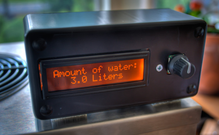
The volume to distill can be selected from 1 to 3 liters (1/1.5/2.5/3).
There is the option to start distillation after a desired period of time.
The LCD displays a summary of the volume to be distilled and (if selected) the delayed start time, with confirmation to begin.
The LCD displays the number of liters distilling and time remaining until the start/finish.
The LCD displays “Caution, Hot” warning for 30 minutes after distillation finishes.
The LCD backlight turns off and the arduino goes into sleep mode when the cool-down warning finishes.
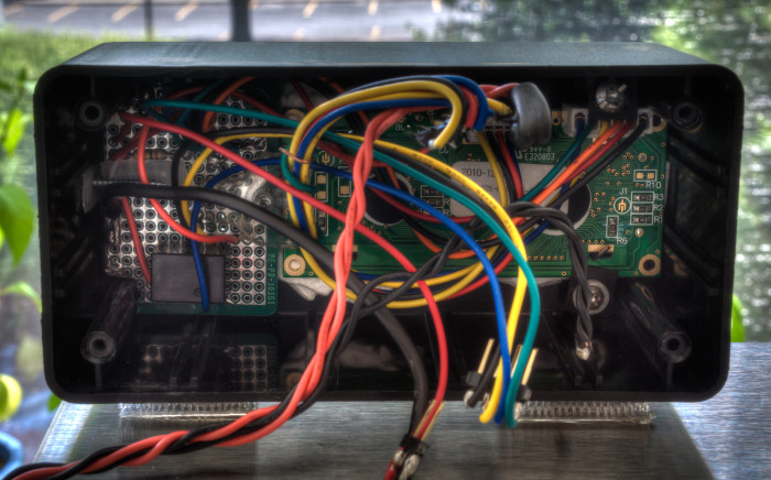
Future plans include removing the arduino board, leaving the ATMega328, once I feel the code has fully matured. I would also like to get my hands on some metal-working tools to put everything behind the metal exterior, for a more polished appearance.
Hello from Argentina (and sorry for my english)!
I’m trying to use your code but when i try to compile have this message:
error: ‘class QuadEncoder’ has no member named ‘hb’
Thanks for your help.
I see this has been solved by you at http://arduino.cc/forum/index.php?topic=154457.0
Nice work!
Hello,
I have realized that I also require distilled water and was wondering if you could lend some guidance in regards to this project?
I noticed you stated that you had distinguished time settings prior to creating the relay controller unit for the distiller, i.e. where you tossed the first 50 mL within the first 25-30 min, but I couldn’t determine an explicit distillation time, per liter of water, afterwards. Would you still have the distillation times used for different volumes of water to be distilled? Also, your explanation eludes to the need for volumetric overages in regards to volume of water to be distilled in order to circumvent the inefficiencies of design with this particular model. Would you happen to have mL of overage per Liter of desired volume of output?
Next, I was wondering if a wiring schematic was available for this project? I intend to use the distiller pictured in the v1.0 project cause it’s cheaper than the big boy distiller pictured in v2.0, at least for the time being.
I have sourced the following parts:
MINI USB Nano V3.0 ATmega328P CH340G 5V 16M Micro-controller board for Arduino
12mm Rotary Encoder Push Button Switch Keyswitch Electronic Components
GORDOS GA5-2D10 SOLID STATE RELAY 3-30 VDC CONTROL 120 VAC OUTPUT
16*2 1602 LCD Board Blue Backlight display Keypad Shield module for Arduino
Will this suffice to accomplish the goals of this project? (sorry n00btastic at arduino stuff)
Thank you very much and I appreciate any help you can provide.
Essentially, you will want to fill the distillation unit with the same amount of water each time. Then measure how long it takes to distill the amount you desire. These times will be what you program the ATMega to cut the power after. If you want to throw away the head (first ~50 ml), you can set up an alarm with a piezo buzzer or similar to go off after that amount has distilled, but I found that it wasn’t really necessary (or at least I couldn’t discern much of a taste difference. V2 has a carbon filter before it collects in the glass jar so removing the head is less important.
As for wiring, I don’t have a schematic on hand (at work), but connecting the relay is pretty easy. Google “arduino relay wiring schematic” and there are numerous examples. The LCD connection will depend on which unit you have. Some are I2C and require only 2 wires (in addition to power and ground), while others require more pins to communicate. The rotary encoder may have a description of the connection in the code. I’ll take a look at it all and the parts you mentioned above, after I get home form work today.
In my v2 code, the rotary encoder connects with ground and 2 pins (digital 4 and 5). Connecting the digital pins either way will work, it will just change the direction turning the knob will navigate through the menu.
For the relay connection, I just posted a schematic for Mycodo on HackaDay, on the Mycod build instructions. Although it’s for the Raspberry Pi, it’s the exact same circuit for the arduino. Your solid state relay I believe is opto-isolated, so it should be fine to hook straight up to the arduino as it’s don’t in the schematic.
Oh the Mycodo instructions are great.
I was interested in the schematics for the distillation controller in this particular post. For the distillation controller I would need a dual port iso optical relay in line with a two port AC terminal plug? In conjunction with the aforementioned sourced parts.
I used two relays, both inline with the AC power. One switched the fan and the other switched the heating element. Because the fan running wasn’t necessary until steam was generated, I switched the heating element on and left the fan off until the water was properly heated. You could have a simpler circuit with one relay and have the fan go on at the same time as the heating element.